Start With the Diagram’s Purpose and Boundaries
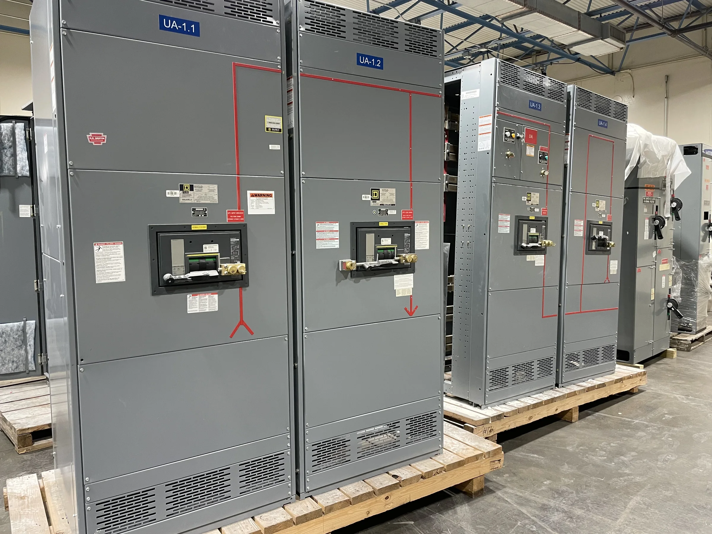
A switchgear control wiring diagram shows how control power, protective devices, operator controls, status indications, and external signals are connected. It is not interchangeable with a one-line diagram, which describes the power system, or a layout drawing, which shows physical arrangement. Before requesting a quote, identify what the diagram must cover: a new lineup, a replacement assembly, a retrofit, or interfaces to existing equipment. Define the equipment lineup and the boundary between manufacturer-supplied wiring and field wiring. This prevents omissions such as an unassigned remote trip input or an unclear terminal block handoff. For new equipment, the manufacturer can develop drawings around the project requirements; the final scope and compatibility depend on the specified application and verified design information.
Document Operating Sequences and Interlocks
A diagram is useful only when it reflects how the equipment is intended to operate. Describe normal, standby, and emergency operating modes, including which devices may close, what conditions prevent operation, and how transfer or tie functions are controlled. Identify required electrical and mechanical interlocks, protective trips, local-versus-remote selection, and alarms. Avoid relying on labels such as “automatic” without explaining the sequence and expected inputs and outputs. A missing permissive or an ambiguous interlock can cause commissioning delays or create an unsafe operating assumption. The project team should review the sequence with engineering, operations, and the equipment supplier before drawings are finalized. Control logic, device selection, and applicable requirements remain project-specific; the diagram should document approved intent, not substitute for it.


Specify Control Power, Devices, and Signals
Procurement documents should identify the control-power source and required voltage, the devices to be controlled or monitored, and any owner-furnished equipment that interfaces with the lineup. List protective relays, metering, switches, indicating lights, trip and close circuits, and communication or supervisory connections where applicable. For each external signal, define its function, normal state, source, destination, and whether it is a contact, powered circuit, or communications point. These details affect component selection, terminal assignments, and coordination with building automation or plant control systems. Do not assume an existing device or protocol will carry over unchanged in replacement work. Confirm interface requirements against current equipment records, and have the responsible engineer verify protection and control choices before release.
Coordinate Drawings With Existing Equipment
Retrofit and replacement projects need more than a preferred control schematic: they need reliable information about the installed lineup and its interfaces. Gather available elementary diagrams, wiring diagrams, terminal schedules, nameplate data, relay settings, and field-marked revisions. Record which circuits and external cables must remain, and identify equipment that will be removed or abandoned. Old drawings may not match field conditions, so discrepancies should be documented and resolved before fabrication rather than discovered during installation. Provide clear equipment designations and consistent circuit references across the one-line, schematics, and connection drawings. This improves review and reduces the chance of mislanding conductors or leaving a required signal unaccounted for. Final fit, electrical compatibility, and the extent of reuse must be evaluated for the specific installation.
Plan Reviews, Revisions, and Schedule Inputs
Control drawings move through a project workflow: requirements are collected, drawings are prepared, stakeholders review them, comments are resolved, and approved documents support manufacturing and installation. Assign reviewers for engineering, operations, controls, and maintenance, and consolidate comments so conflicting revisions do not circulate. Identify the approval milestone and any required document formats or submittal records in the purchase specification. Schedule depends on the completeness of those inputs, design decisions, component availability, and the agreed review process; a manufacturer’s short-lead-time offering is not a guaranteed delivery date for every configuration. Clarify the requested ship date, required on-site date, and any commissioning dependencies early. Nationwide shipping can support projects across the U.S., but receiving access and site readiness still need coordination.
Prepare Site Handoffs and Closeout Records
Before equipment arrives, confirm the delivery route, unloading method, receiving hours, staging area, and any limits on truck access, door openings, floor loading, or laydown space. These constraints can affect shipment planning and the sequence for moving sections into an electrical room. At the same time, define who will terminate field wiring, verify point-to-point connections, and witness functional checks after installation. The delivered drawing package should be coordinated with approved revisions and clearly distinguish factory wiring from field connections. Request the records needed for maintenance and future troubleshooting, such as final wiring diagrams, terminal information, and applicable equipment documentation. Keep the approved sequence and as-built changes available to facility staff. Installation, inspection, testing, and energization must follow project requirements and be performed by qualified personnel under appropriate safety procedures.