Start with the Load Profile, Not a Catalog Frame
A reliable switchgear design begins with a clear picture of what the equipment must serve and how those loads behave. Document normal demand, expected growth, large motor starts, nonlinear loads, and any equipment that must remain supplied during an outage. These details influence bus capacity, feeder arrangement, protective-device selection, and the space reserved for future circuits. A panel schedule alone may not reveal operating sequences or critical-load priorities, so include one-line diagrams and control narratives where available. For a replacement, record existing ratings and field conditions without assuming the old arrangement is suitable for the new installation. Early review helps identify missing information before fabrication planning, reducing avoidable revisions while keeping final ratings and compatibility subject to engineering review.
Coordinate Protection, Fault Duty, and System Interfaces
Protective devices must be considered as part of the electrical system, not selected only by ampere rating. Provide available fault-current information, upstream and downstream device data, grounding details, and the intended coordination objectives. A change in transformer size or impedance, utility service, generator contribution, or feeder length can affect fault duty and protection requirements. That matters because equipment ratings and device settings must suit the actual system, while coordination goals may involve tradeoffs between selectivity and rapid fault clearing. Ask the project engineer to identify required studies, submittals, and review responsibilities. Do not assume existing settings or drawings remain valid after a system change. Confirm applicable codes, standards, and project criteria for the specific installation before releasing the design.


Make the Enclosure Fit the Room and the Work
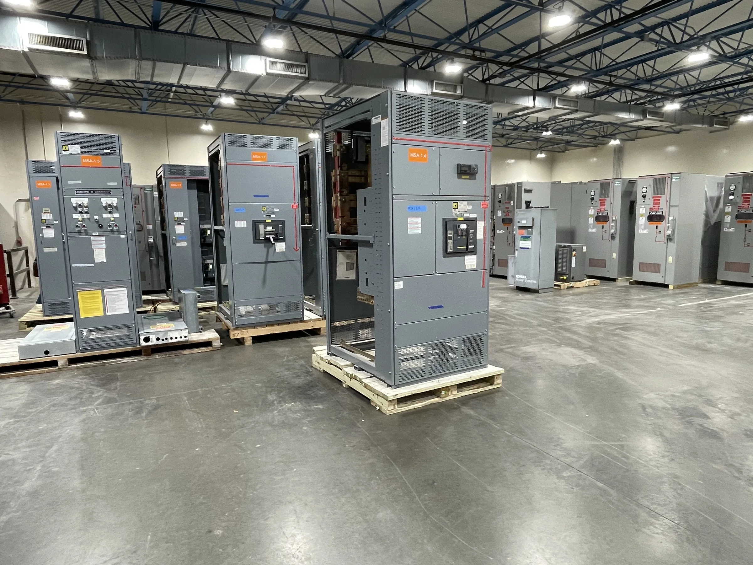
Room conditions can constrain a design as much as the electrical load. Verify available floor area, ceiling height, access routes, door and aisle clearances, cable entry direction, and the space needed to install and service the assembly. Note ambient temperature, moisture, dust, corrosive exposure, and indoor or outdoor placement; these conditions can affect enclosure choices and project-specific suitability. For retrofit work, measure the actual room and record obstructions rather than relying on old drawings. Check that the planned shipping sections can pass through doors, elevators, corridors, or loading areas and reach the final location. A design that fits electrically but cannot be moved into position can trigger costly field changes, so resolve access and handling constraints before approving layouts.
Specify Components and Construction with Clear Boundaries
A useful specification distinguishes required performance from preferred construction details. Identify voltage, phase, frequency, continuous-current needs, short-circuit information, incoming and outgoing arrangements, metering, control power, and any communications interfaces. State preferences for American components when they are part of the project brief, but list acceptable manufacturers or substitutions only through an agreed review process. Define which party supplies protection studies, utility requirements, field wiring, and commissioning so that interface gaps do not surface during installation. For low-voltage switchboard assemblies, UL 891 may be relevant when the assembly is appropriately evaluated; it is not a blanket certification for medium- or high-voltage equipment. Confirm the applicable standard, labeling expectation, and documentation for the exact assembly before purchase.
Plan Schedule Around Submittals, Decisions, and Site Readiness
A short manufacturing lead time is useful only when engineering inputs and approvals arrive in time to support the project schedule. Build the procurement plan around confirmed scope, drawing review, customer comments, approved submittals, component decisions, and any required utility or engineer approvals. Ask the U.S. manufacturer to discuss current timing for the specific configuration, since custom construction and component availability can affect the schedule. Identify decision dates for metering, communications, device preferences, and cable entry before they become late changes. In parallel, confirm when foundations, conduits, access, and receiving arrangements will be ready. Treat delivery estimates as project-specific rather than guaranteed. Clear review ownership and prompt resolution of open items help protect the installation window without sacrificing technical checks.
Document Delivery, Installation, and Future Maintenance Needs
Before shipment, align the equipment drawings and approved submittals with the site team’s installation plan. Confirm shipping dimensions and weights, unloading responsibility, delivery appointment requirements, storage conditions, and the route from the receiving area to the electrical room. Nationwide shipping can support projects across the United States, but the site must still be prepared to receive and handle the particular assembly safely. Keep current one-line diagrams, wiring diagrams, device information, approved settings, and operation and maintenance documents with the facility’s records. During planning, define the inspection, testing, commissioning, and acceptance responsibilities; project requirements vary, and no test result should be assumed in advance. Accurate records help maintenance staff understand the installed configuration and evaluate later changes without relying on outdated field assumptions.