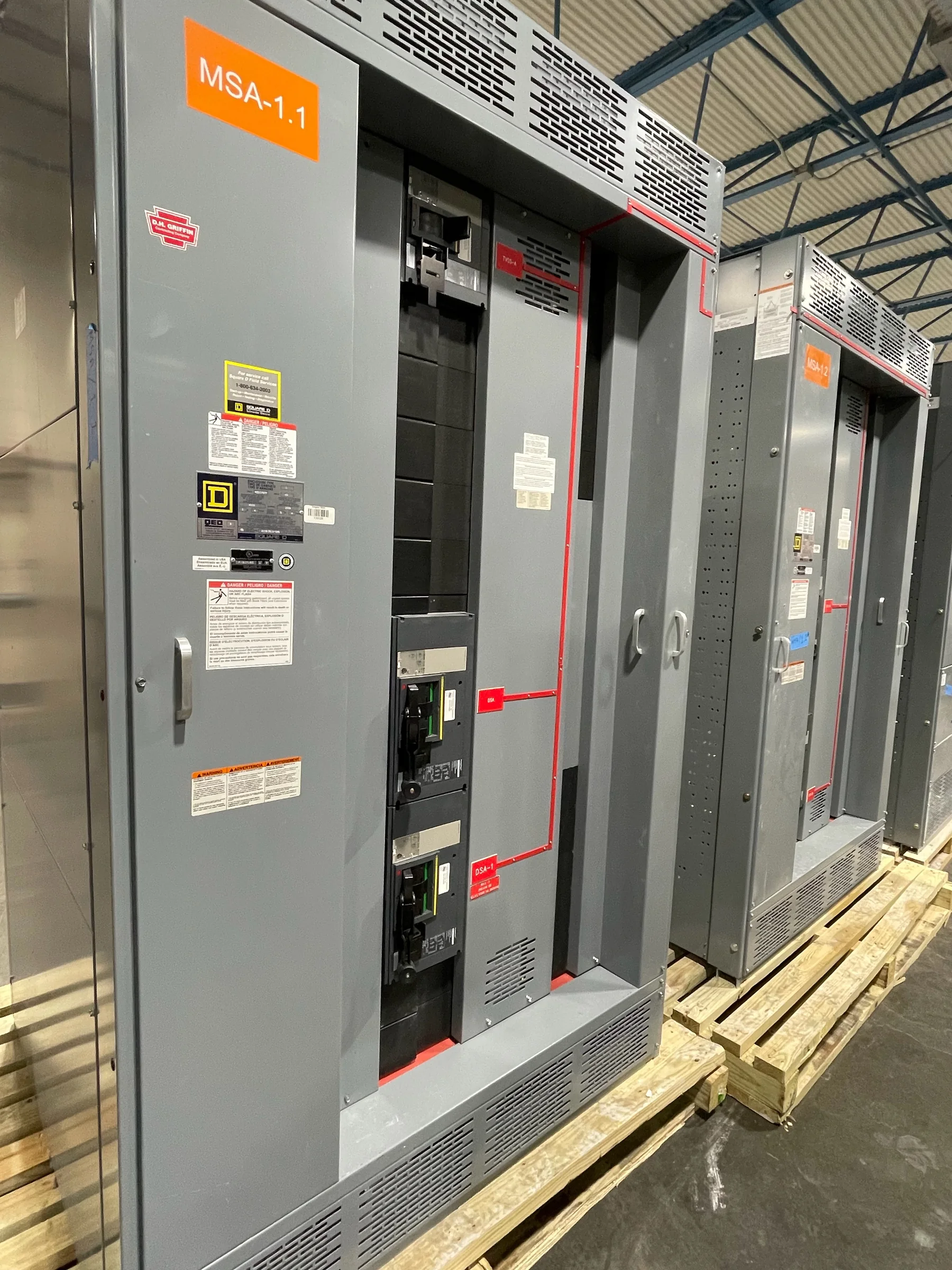
Start With the Feeder’s Electrical Duty
A feeder breaker should be selected from the circuit it must protect, not from a preferred frame size or a spare space in an existing lineup. Gather the system voltage and phase, feeder load and demand assumptions, conductor details, and the available fault-current information at the proposed equipment location. The engineer can use these inputs to evaluate continuous current, interrupting capability, short-circuit rating, and protection settings in the context of the source and downstream devices. Motor starting, transformer inrush, long cable runs, and future load growth can change the application. If fault-current or load data is preliminary, identify the assumption and who will confirm it; otherwise, a quote may be based on a duty the final design cannot support.
Coordinate Protection With the Whole Distribution System
Breaker trip functions and settings affect more than the feeder alone. Review the upstream main, alternate sources, downstream breakers, ground-fault protection where applicable, and any generator or tie operation that changes available current. A coordination study can show whether a fault is likely to disconnect only the affected feeder or interrupt a larger portion of the facility. Arc-flash analysis and incident-energy requirements may also influence protective-device choices, labeling, and operating procedures. Provide current one-line diagrams and study files rather than relying on settings copied from an older installation. Final coordination depends on the complete system and selected devices, so confirm settings with the responsible engineer before release. Equipment selection does not replace safe work practices; installation and maintenance planning must account for de-energized work.


Define Breaker Construction and Control Needs
Specify how the feeder breaker will be operated and maintained. A fixed-mounted device and a drawout arrangement differ in access, maintenance planning, space needs, and the equipment interfaces required; neither should be assumed compatible with an existing lineup without verification. State whether operation is manual or electrical, and identify requested auxiliary contacts, shunt trip, undervoltage release, metering, communications, or interlocking. These features affect wiring, control power, terminal locations, and the drawings technicians will use later. For replacement or retrofit work, send equipment nameplate data, interior and exterior photographs, breaker details, bus and cable connection information, and measured clearances. Similar-looking equipment may have different dimensions or connection patterns. The manufacturer can review the supplied information, but final fit and application remain project-specific.
Resolve Ratings, Standards, and Documentation Before Release
A complete purchase specification lets engineering, procurement, and the manufacturer work from the same basis. Include the one-line diagram, feeder schedule, load and fault-current data, breaker functions, enclosure and environmental requirements, cable entry direction, and any required monitoring or control interfaces. Identify applicable project standards and whether the requested assembly is a low-voltage switchboard or another equipment class; UL 891 applies to appropriately evaluated switchboard assemblies, not as a blanket certification for medium- or high-voltage equipment. Request submittal drawings for review and document approved deviations before fabrication. Confirm the scope of any requested label or listing for the exact assembly rather than assuming it from a general product description. American components and custom-build options can be discussed against the approved design and project requirements.
Build a Realistic Schedule Around Decisions and Shutdowns
Project timing depends on more than fabrication. Identify when drawings must be approved, when site measurements or utility data will be available, and when the facility can accept equipment and schedule installation. Late changes to breaker accessories, cable entry, lineup arrangement, or fault-duty information can require engineering review and affect the agreed schedule. For an operating facility, coordinate the replacement window with operations, contractors, commissioning staff, and the authority having jurisdiction as needed. Establish who owns each approval and what information must be closed before release. A U.S. manufacturer may offer short lead times, but exact availability and delivery timing depend on the approved configuration, component supply, and project conditions. Ask for a project-specific schedule and confirm it again if requirements change.
Plan the Route From Truck to Final Position
Delivery planning should begin with the equipment outline, shipping configuration, and site access—not when the truck is already at the gate. Check door and corridor clearances, turning space, floor loading, overhead obstructions, receiving hours, unloading equipment, and the path to the electrical room. Confirm whether the lineup ships in sections and how those sections will be staged, moved, and joined at the site. Keep the installation area accessible and compare the final foundation, working clearances, conduit locations, and cable approach with the approved drawings before shipment. Nationwide shipping supports projects across the United States, but freight arrangements, site restrictions, and receiving responsibilities need project-specific confirmation. Include the delivery contact, appointment process, unloading plan, and any limits on storage so arrival does not create avoidable schedule or handling problems.