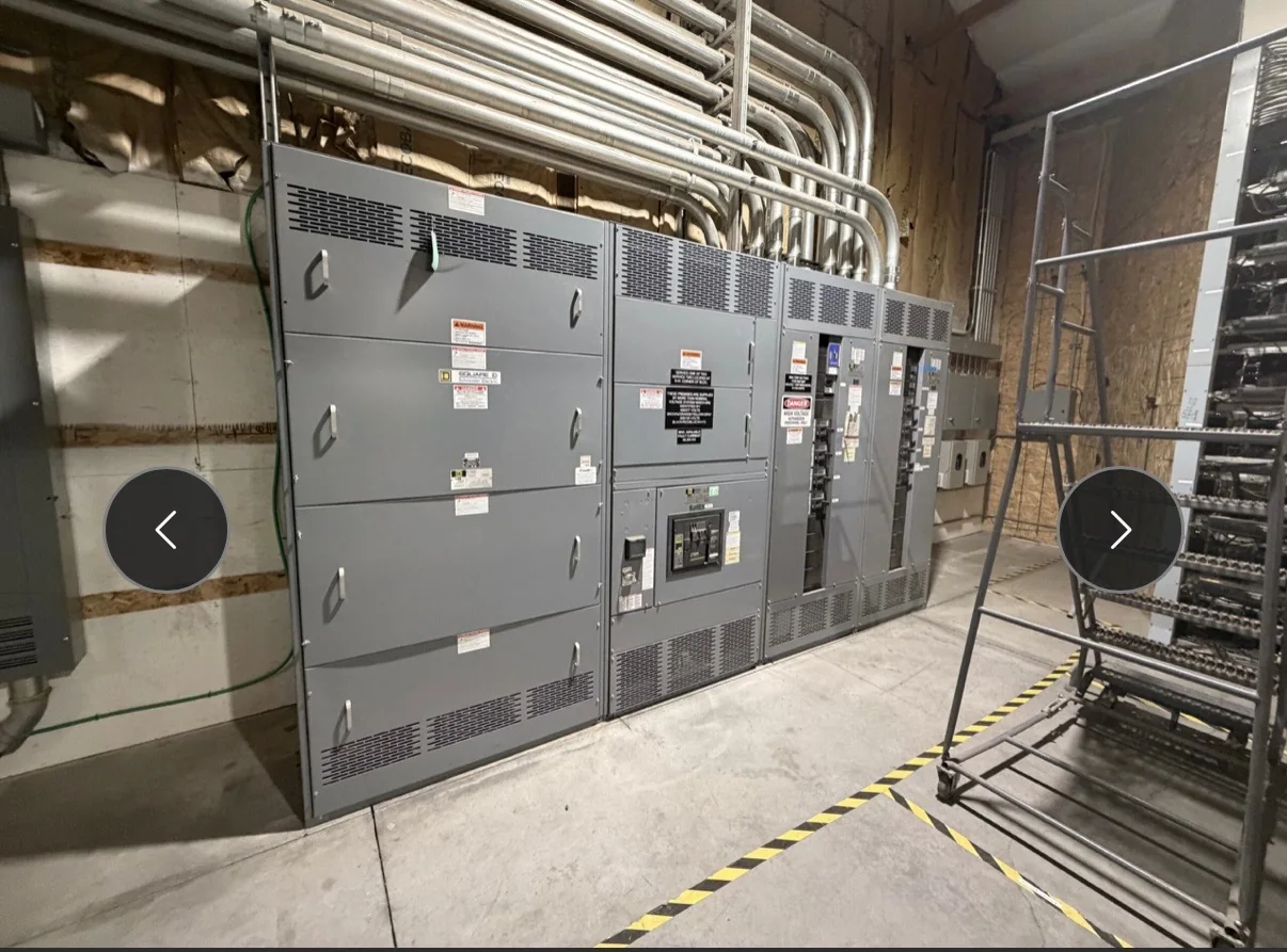
Define the Generator’s Role Before Selecting Switchgear
Start by establishing what the generator must support: the entire facility, designated life-safety or critical loads, or selected process equipment. That decision affects bus capacity, feeder arrangement, transfer equipment, protective-device coordination and the space reserved for future circuits. Document the generator’s voltage, phase, frequency, grounding method and available fault current, along with the intended operating modes. A standby source that serves only a portion of the load may require a different lineup and transfer scheme than a source used for broader backup or parallel operation. Do not assume existing switchgear can accept a generator connection because the nominal voltage matches. A manufacturer can develop a proposed configuration from project criteria, but final equipment ratings and compatibility depend on the complete system design and review.
Coordinate Transfer, Paralleling and Control Requirements
The one-line diagram should show how the generator connects to the distribution system and how loads move between normal and alternate sources. Specify whether the project calls for automatic transfer, open or closed transition, load shedding, or paralleling; these are distinct functions with different equipment and control implications. Include the intended sequence of operation, source permissives, interlocks, alarms and any required interface with a building management or generator control system. Ambiguity at this stage can lead to mismatched controls, late drawing revisions or a lineup that cannot deliver the intended operating sequence. Ask the electrical engineer, generator supplier and switchgear manufacturer to review the same control narrative and interface points. Confirm project-specific code and authority requirements through the responsible design professionals and local permitting process.


Check Electrical Ratings and Protection as a System
Generator integration changes the sources contributing fault current, so protective-device selection cannot be based on utility conditions alone. Provide available short-circuit information for each source and operating mode, protective-device settings or coordination criteria, grounding details, and any arc-flash or selective-coordination requirements established by the design team. The engineer should assess how generator fault contribution, transfer positions and parallel operation affect interrupting ratings and protection. A switchboard’s bus rating, service conditions and device arrangement must suit the actual application; nominal voltage by itself does not establish suitability. If low-voltage switchboard assemblies are being considered, UL 891 may be relevant when the particular assembly is appropriately evaluated. It is not a blanket designation for medium- or high-voltage equipment, nor a guarantee that every proposed configuration carries a UL label.
Plan the Physical Interface at the Generator and Site
Electrical fit is only part of integration: the generator connection, cable or busway route, enclosure location and access for installation all require coordination. Share a dimensioned site plan, equipment-room layout, generator terminal information, cable-entry preferences and available working clearances during quotation and drawing review. Consider heat, ventilation, vibration, exhaust separation, weather exposure and the path used to move equipment into the building. These conditions can affect enclosure selection, connection details and lineup segmentation, but the design must be confirmed for the specific installation. Check door swing, overhead obstructions, floor loading and turning space before approving dimensions; a lineup that fits on paper may be difficult to place or service. Resolve who supplies connecting conductors, lugs, conduit, controls wiring and field terminations in the project scope.
Build a Quote Package That Supports Accurate Review
A useful request for quotation includes the one-line diagram, load schedule, equipment specifications, sequence of operation, site constraints and project schedule. Identify the requested source and load arrangement, nominal system data, available fault-current information, enclosure environment, metering needs, communications interfaces and any owner or engineer standards. Mark requirements as mandatory or preferred, and flag information that remains under development rather than allowing assumptions to become hidden design inputs. Ask the manufacturer to identify exceptions, required clarifications and items supplied by others in its proposal. This makes competing offers easier to compare and reduces the risk of overlooking control components or connection hardware. Exact ratings, standards, evaluations, price and availability depend on the final scope, engineering review and applicable project requirements; request confirmation before treating any selection as approved.
Align Submittals, Production and Delivery With Site Readiness
Custom equipment requires a schedule that accounts for design approval as well as manufacture and transportation. Establish review dates for outline drawings, one-line diagrams, control schematics and connection details, then assign reviewers who can resolve comments promptly. Confirm the approved configuration before release; changes to breaker selections, cable entry, metering or control interfaces can affect drawings and production planning. Ask for current availability and a project-specific delivery estimate rather than relying on a general lead-time statement. Before shipment, coordinate receiving hours, unloading equipment, route dimensions, storage conditions and the destination’s ability to protect the lineup from moisture or damage. Nationwide shipping does not remove the need for site coordination. Keep the installation contractor, generator supplier, engineer and facility representative aligned on shipment milestones, field connections, testing responsibilities and required de-energized work.