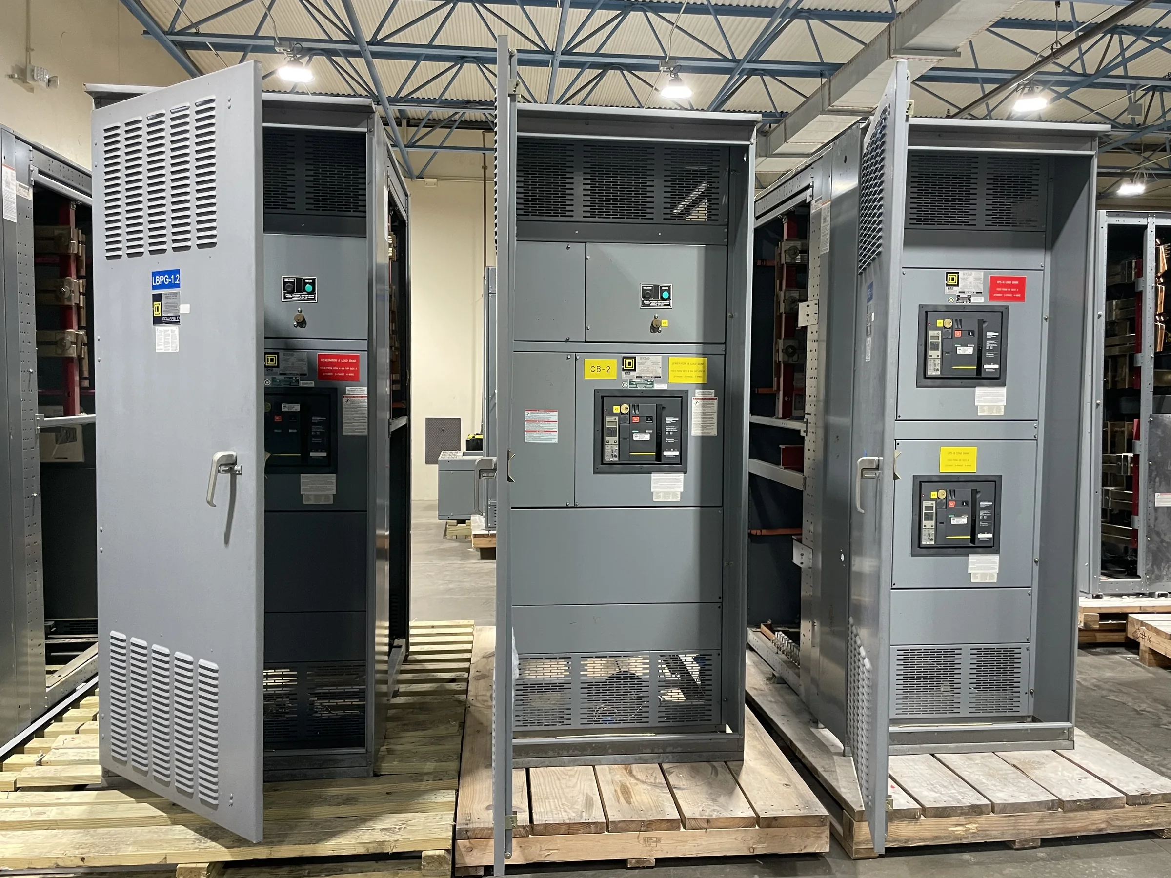
Define the Ground Bus Function Before Setting Its Size
A switchgear ground bus is part of the equipment’s grounding and bonding path; it is not a substitute for the facility grounding-electrode system or a protective device. Begin the specification by identifying what the bus must connect: enclosure sections, doors or barriers where bonding is required, equipment grounding conductors, and the site grounding network. The available fault-current information and the protective devices’ clearing characteristics affect the thermal and mechanical duty the grounding path must withstand. These inputs should be coordinated by the project’s electrical engineer rather than inferred from the switchgear’s ampere rating. For a new assembly, provide the one-line diagram, system voltage, source information, and applicable project criteria so the manufacturer can review the intended arrangement and identify missing design inputs.
Coordinate Fault Duty, Protection, and Applicable Standards
Ground-bus adequacy depends on the available ground-fault current and how quickly upstream protection clears a fault. A high available fault current with a delayed clearing time can impose a different thermal duty than a lower current cleared promptly; conductor size alone does not establish suitability. The engineer should provide the calculated fault-current conditions at the equipment location and the protective-device assumptions used in the study. Identify the governing project standards and required evaluation for the complete assembly. UL 891 applies to appropriately evaluated low-voltage switchboard assemblies; it should not be treated as a blanket certification for medium- or high-voltage equipment, or as proof that every configuration carries a UL label. Confirm the exact equipment scope, evaluation requirements, and labeling expectations before approving submittals.


Map Bus Joints, Section Bonds, and Field Connections
The physical path through the gear matters as much as the bus material or nominal dimensions. Review how ground-bus segments join between shipping sections, where field connections land, and whether the proposed locations remain accessible after the lineup is installed against walls or adjacent equipment. Section joints and bolted connections must preserve reliable electrical continuity; paint, coatings, hardware selection, and specified surface preparation should be addressed in the assembly design rather than left to field interpretation. Show the bus route and connection points on equipment drawings, including any interface with external grounding conductors. If the lineup has multiple sections or unusual transitions, resolve those details during submittal review. Clear joint documentation reduces installation questions and helps prevent a visually complete lineup from having an overlooked bonding connection.
Specify Material, Environment, and Corrosion Considerations
Choose ground-bus material and finish for the actual installation environment, not simply by copying a prior project’s schedule. Moisture, corrosive atmospheres, conductive dust, temperature, and indoor or outdoor exposure can affect material selection, surface finish, and connection details. Explain the conditions the equipment will face and identify any enclosure or environmental requirements that influence the bus arrangement. If dissimilar metals or field-installed connectors are part of the interface, ask the design team to confirm compatible materials and connection methods. These choices matter because corrosion or an unsuitable interface can compromise bonding continuity over time, even when initial assembly fit is acceptable. Document environmental assumptions in the equipment specification and drawings so procurement, factory design, and site installation are working from the same conditions.
Prepare Submittals Around the Real Site Interfaces
A complete procurement package helps keep ground-bus details from surfacing as late installation changes. Include the one-line diagram, equipment schedule, available fault-current data, protection study assumptions, grounding details, site conditions, and required project standards. Identify the incoming grounding-conductor route, termination preferences, access restrictions, and any connection to existing equipment or a facility ground grid. Provide room layouts and dimensions that show cable-entry direction, working clearances, housekeeping pads, doors, and nearby obstructions. These constraints can affect bus position, section arrangement, and the practical sequence for making connections. Require review of drawings showing bus location, section joints, and field interfaces. Resolve discrepancies between drawings and specifications before release for manufacture; changing a connection point after fabrication can affect both schedule and installation planning.
Plan Manufacturing Release, Shipment, and Installation Sequencing
Discuss schedule and delivery as project-specific planning items, not fixed promises. Custom equipment depends on approved design inputs, drawing review, material availability, manufacturing requirements, and the release date; confirm current timing with the manufacturer for the quoted scope. Before shipment, coordinate the lineup’s shipping-section breakdown, site access, unloading method, indoor storage, and the route from receiving area to electrical room. Ground-bus connections between sections may require field assembly, so confirm what is factory-installed and what the installation documents require the contractor to complete. Nationwide shipping does not remove the need to plan truck access, lifting equipment, staging space, or protection from weather and construction debris. Keep the equipment de-energized during installation and inspection, and have qualified personnel follow approved project procedures before placing it in service.