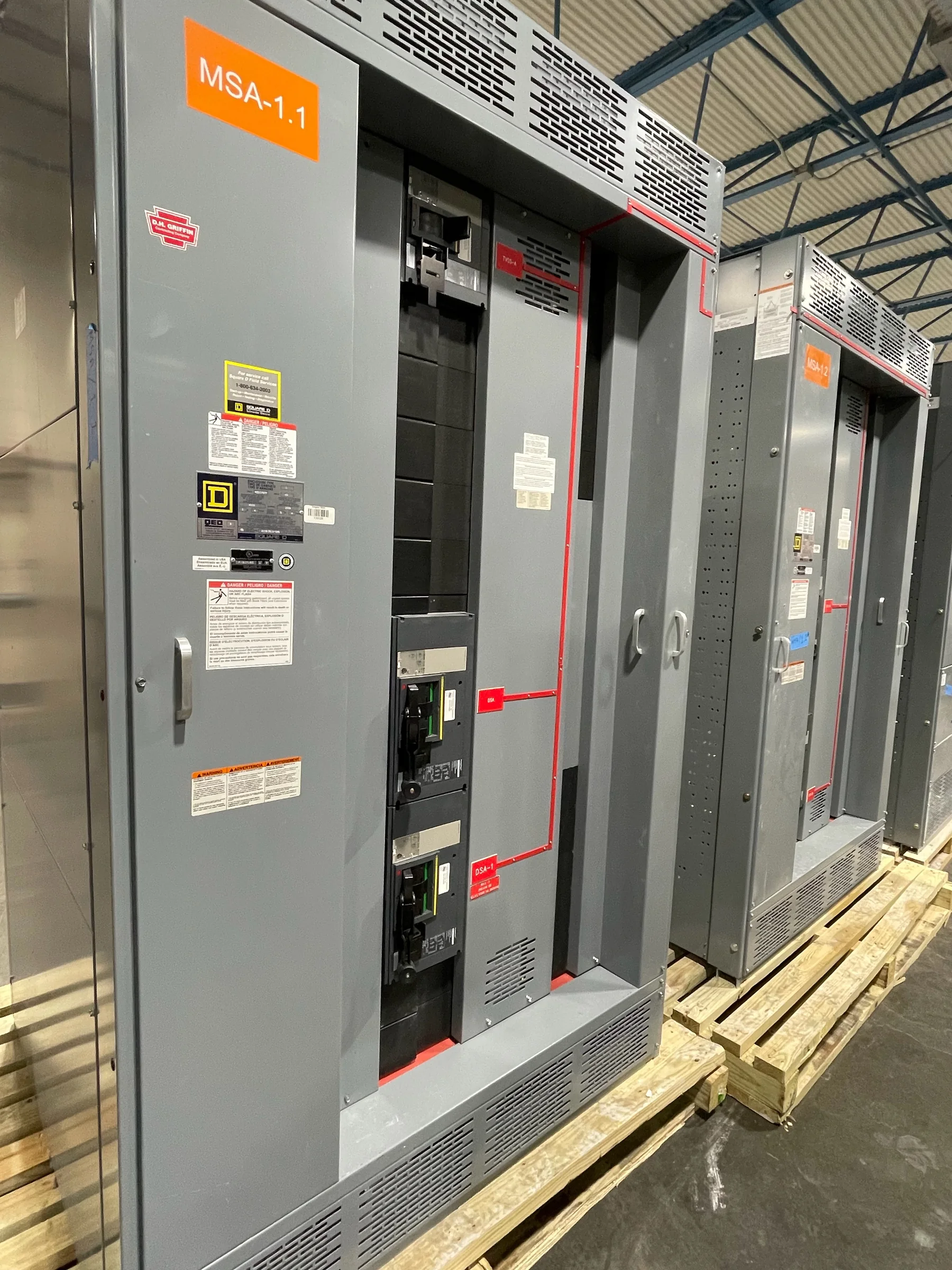
Define What the Protection Must Detect
Ground-fault protection is intended to detect current leaving its intended circuit path, but the right arrangement depends on the system grounding method, voltage, and distribution layout. Begin with a one-line diagram that identifies the source, transformer connections, grounding points, and downstream protective devices. Ask the engineer to clarify whether the objective is equipment protection, personnel protection, service continuity, or a coordinated combination; these goals can lead to different sensing and tripping decisions. A ground-fault function is not a substitute for grounding, bonding, insulation maintenance, or a complete protection study. For new switchgear, provide the manufacturer with the design basis and operating priorities early. Exact functions, ratings, and applicability are project-specific and require engineering review.
Coordinate Sensors, Trip Units, and Breakers
A protection scheme works only when its sensing method and trip response match the circuit arrangement. Depending on the design, ground-fault sensing may use phase-current summation, a neutral sensor, or another engineered configuration; the correct choice depends on conductor routing, system grounding, and the equipment’s protective devices. Share breaker and trip-unit requirements, available fault-current information, and any existing coordination study with the switchgear supplier and responsible engineer. Sensor placement and neutral treatment matter: an omitted or incorrectly routed neutral can affect measurement and produce nuisance operation or missed detection. Confirm how the intended function integrates with upstream and downstream protection, including settings access and indication. Do not assume a familiar device or setting transfers unchanged to a new assembly.


Make Coordination and Continuity Objectives Explicit
Ground-fault settings should be evaluated as part of the complete protective-device coordination, not selected in isolation. A trip threshold or delay that is too sensitive for normal system conditions can interrupt service unnecessarily; one that is too permissive may not provide the intended protection. The engineer should assess the available fault-current conditions, equipment limits, downstream devices, and operating modes, documenting the basis for proposed settings. Consider whether alternate sources, generator operation, or tie-breaker configurations change the ground-fault paths or coordination. Facilities with process-critical loads should identify which interruptions are acceptable and which require planned sequencing or operational procedures. Final settings and performance depend on the project-specific study, installed devices, and commissioning verification—not a generic factory default.
Send a Complete, Reviewable RFQ Package
A detailed request for quotation reduces avoidable design assumptions and clarifications. Include the one-line diagram, equipment schedule, system voltage and frequency, grounding method, source information, requested ground-fault functions, breaker data, and applicable project specifications. Identify the required configuration, enclosure and environmental conditions, cable-entry direction, bus connections, control-power expectations, metering or communications interfaces, and any specified standards or owner requirements. Mark which details are confirmed and which remain under engineering review; this helps the manufacturer identify open decisions without treating preliminary information as final. If a low-voltage switchboard is being considered, UL 891 may be relevant to an appropriately evaluated assembly, but it is not a blanket claim for all switchgear or medium-voltage equipment. Confirm project-specific evaluation and documentation requirements.
Plan Schedule Around Design Decisions and Reviews
Procurement timing depends on more than the date a purchase order is issued. Unresolved grounding details, protective-device selections, interface points, or submittal comments can hold up design release and affect manufacturing sequence. Ask for a project-specific schedule that identifies required customer inputs, drawing review milestones, approval responsibilities, and any dependencies on equipment by others. Short lead times may be available for some custom builds, but timing is not guaranteed and depends on the approved scope, component availability, and production requirements. Changes after approval can require engineering review and may alter the schedule. Establish one channel for consolidated comments, identify who can approve settings and drawings, and resolve exceptions before release. Treat quoted timing as subject to confirmation against the final approved configuration.
Coordinate Delivery, Installation, and Verification
Before shipment, verify that the route from receiving area to electrical room can accommodate the specified sections, handling equipment, door openings, floor loading, and turning space. Confirm shipping splits, lifting or moving restrictions, laydown space, and any site-specific access or delivery-hour rules with the manufacturer and carrier. At the installation stage, the qualified project team should follow approved drawings and applicable procedures, keep equipment de-energized for installation and inspection, and verify grounding, connections, sensors, and protective-device configuration before energization. Commissioning records should capture test scope, device identification, settings, and unresolved exceptions so future maintenance teams can understand the protection scheme. Coordinate shipment dates with site readiness; nationwide delivery does not remove the need to confirm receiving capacity, unloading arrangements, and project-specific transit details.