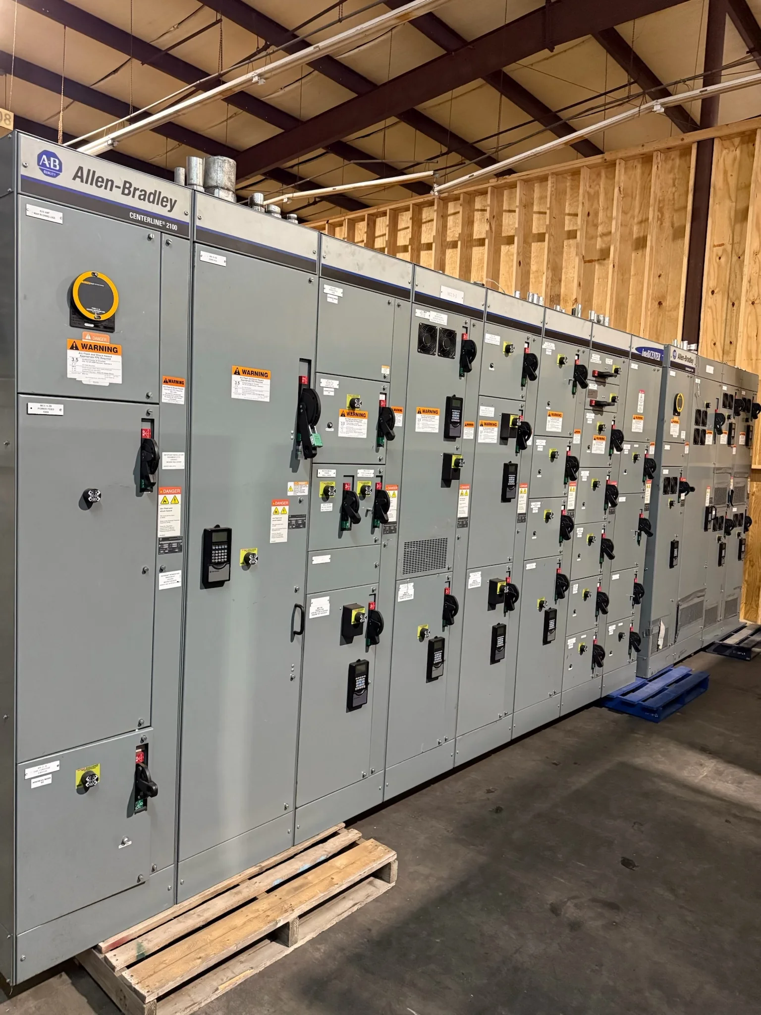
Start With the Room, Not Just the Switchgear
An indoor switchgear room has to accommodate the equipment, the people who operate and maintain it, and the building systems that support it. Begin with a dimensioned room plan showing walls, columns, doors, structural openings, overhead obstructions, and the intended equipment lineup. Identify whether the project calls for low-voltage switchboards, medium-voltage gear, or multiple assemblies; their footprints, access needs, and interconnections can differ substantially. Confirm the electrical one-line diagram, voltage, system configuration, and required ratings with the responsible engineer before fixing the layout. These inputs matter because late changes to lineup length, cable entry, or equipment arrangement can conflict with the building plan and disrupt procurement. Final requirements and equipment compatibility are project-specific.
Map Working Space, Doors, and Service Access
A room layout must preserve the clearances and access required by applicable codes, equipment instructions, and the project engineer—not merely leave enough space to place the lineup. Show working space at the equipment faces, door swings, exit paths, and access to controls and removable components. Consider how technicians will open compartments, position tools, and perform maintenance under the facility’s approved safety procedures. A door that clears an aisle when shut may obstruct the working area when open; a narrow route can also prevent replacement components from reaching the equipment. Have the electrical engineer verify the required clearances and egress provisions for the actual installation. Document these checks on the plan so purchasing, construction, and inspection teams are coordinating around the same constraints.


Resolve Cable Entry and Building Interfaces
Cable routing is a layout decision with consequences for both the room and the equipment configuration. Establish whether conductors enter from above, below, or another approved direction, and coordinate that choice with the lineup arrangement, pull space, conduits, trenches, and structural penetrations. Show transformer locations, bus connections, grounding provisions, and any planned future feeders where they affect the room plan. A crowded cable approach can make installation and termination difficult, while an uncoordinated floor opening may conflict with foundations or building services. Share the latest one-line, cable schedule, equipment arrangement, and architectural or structural drawings with the manufacturer and design team. Entry details, bending space, terminations, and compatibility must be confirmed for the selected equipment and project.
Account for Heat, Environment, and Room Services
Indoor equipment still depends on its surrounding environment. Coordinate ventilation or cooling with the electrical design, including the expected room conditions and heat load for the selected assemblies. Review exposure to dust, moisture, corrosive substances, vibration, and other industrial conditions; these may influence equipment construction, enclosure choices, room finishes, or maintenance planning. Keep piping, drainage, and unrelated building services from creating avoidable exposure or restricting access, and identify fire-protection and detection interfaces for the project team to resolve. Do not assume that an indoor location alone establishes an acceptable environment or enclosure. Document the operating conditions and applicable design criteria early, then confirm suitability with the responsible engineer and manufacturer. Environmental requirements and product options depend on the specific application.
Coordinate Specifications, Submittals, and Schedule
A complete purchasing package helps the manufacturer build equipment to the project’s actual requirements. Provide the one-line diagram, equipment schedule, room plan, required ratings, control and metering needs, cable-entry preferences, and applicable project standards. Note interfaces with protective relays, transformers, generators, or building systems where they affect arrangement or supply. For a low-voltage switchboard, UL 891 applies only when the assembly is appropriately evaluated; it is not a blanket designation for medium- or high-voltage gear. Request a quote against the defined scope and review submittal drawings before releasing construction details that depend on equipment dimensions. Discuss timing with the U.S. manufacturer at the specification stage: build sequence, approvals, component availability, and scope can affect schedule, so delivery dates must be confirmed for the project.
Plan the Route From Shipment to Final Placement
A layout is not complete until the equipment can reach its final position. Check the route from the unloading area through gates, corridors, doors, elevators, and turns; compare clear openings and floor capacity with the approved shipping configuration. Identify laydown space, lifting restrictions, weather exposure during handling, and any need to coordinate delivery with construction access or other trades. Nationwide shipping can support projects across the United States, but the site team must confirm receiving arrangements, shipment details, and delivery timing for its location. Show the intended final lineup position and any assembly or joining constraints on coordinated plans. Before installation, verify that the room is ready and that the equipment matches approved documents; placement and connection work must follow project procedures and be performed by qualified personnel.