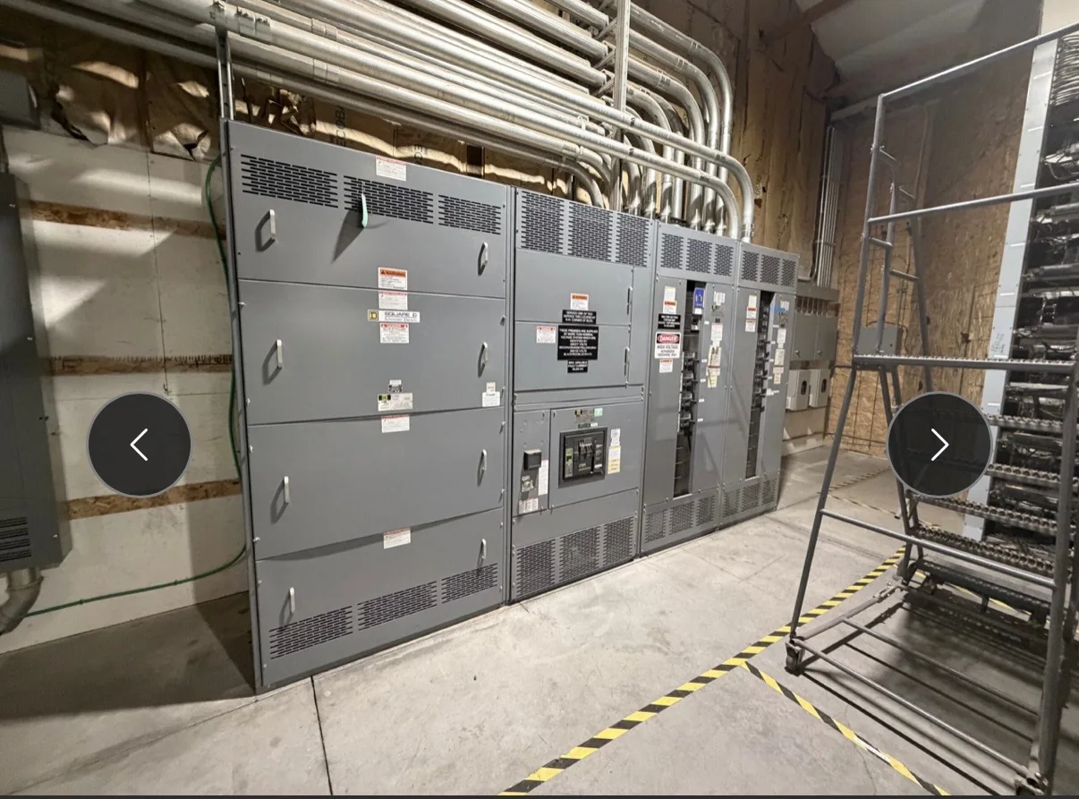
Set the Equipment Scope Before Installation Planning
Begin coordination by defining what the new switchgear must serve and where the contractor’s scope begins and ends. Identify the source and downstream loads, existing equipment to be replaced, required lineup arrangement, and whether the project involves a switchboard or medium-voltage gear. That distinction affects equipment selection, submittal expectations, interfaces, and which standards may apply; UL 891 concerns appropriately evaluated low-voltage switchboard assemblies, not medium-voltage equipment generally. Document system voltage, phase, frequency, fault-current information, grounding approach, and the protection and metering functions required, with the engineer responsible for confirming design inputs. Clear scope prevents assumptions about included breakers, accessories, bus connections, or field modifications from surfacing after fabrication or at the installation site.
Coordinate Contractor Inputs During Submittal Review
The installation contractor, engineer, and equipment manufacturer should resolve physical and electrical interfaces while drawings are being reviewed, not after the lineup arrives. Check approved layout drawings against the room plan, cable-entry direction, conduit locations, bus connections, anchorage details, and access needed for assembly and maintenance. Confirm who supplies transition sections, external bus, lugs, grounding connections, control wiring, and any required field-installed accessories. Review protection settings and control schematics with the responsible design and commissioning teams; do not treat a typical arrangement as confirmation of project-specific compatibility. A marked-up submittal set can expose conflicts between equipment dimensions and construction documents early, when a design adjustment is easier to coordinate than a field change affecting adjacent trades or energization milestones.


Build a Realistic Schedule Around Approvals and Interfaces
A practical procurement schedule accounts for engineering review, drawing approval, release to production, site readiness, shipping coordination, installation, and testing. Establish which party owns each decision and when that decision is needed; unresolved ratings, connection details, or accessory selections can delay approval and affect the manufacturing sequence. Discuss current availability and anticipated timing directly with the U.S. manufacturer, and treat any schedule estimate as project-specific rather than guaranteed. Align equipment milestones with the contractor’s outage plan, construction sequence, and commissioning window, including time for receiving inspection and correction of documented shipping damage. If the project has phased installation or temporary power requirements, show those dependencies in the schedule so procurement decisions do not inadvertently constrain continuity of operations.
Verify the Room, Route, and Receiving Plan
Before shipment, the contractor should compare the approved equipment configuration with actual site conditions and the complete route from the delivery point to the electrical room. Check door and corridor clearances, floor openings, turning space, overhead obstructions, unloading access, and any building restrictions affecting handling. Confirm shipment breakup and lifting or rigging responsibilities with the project team; do not assume a lineup can pass through an opening or be moved using an unverified method. Review floor loading and housekeeping-pad or anchorage requirements with the appropriate engineer, because a suitable room layout alone does not establish structural adequacy. Coordinate delivery timing with site staffing, storage conditions, and protection from moisture, dust, and construction activity, then document who inspects and reports discrepancies.
Align Field Work, Safety, and Commissioning Responsibilities
Installation documents should distinguish manufacturer instructions from contractor means and methods, engineering requirements, and commissioning procedures. Assign responsibility for setting and joining sections, field bus connections, grounding, conduit and cable work, control wiring, torque records where required, and closeout documentation. Confirm that the qualified personnel performing the work have the approved drawings, applicable instructions, and a process for resolving discrepancies before proceeding. Electrical work must follow applicable safety procedures; de-energized work and verification of an electrically safe work condition are not optional planning details. Coordinate inspection and test responsibilities with the engineer, contractor, and commissioning provider, including prerequisites such as completed connections, reviewed settings, and approved test procedures. Clear handoffs reduce missed checks and help prevent energization before the equipment and connected system are ready.
Close Out Procurement and Change Control Clearly
Keep the final approved submittals, equipment schedule, purchase-order scope, shipping records, field change log, and commissioning documentation together as the project record. When a site condition changes, route the proposed adjustment through the responsible engineer and manufacturer before altering equipment, protection, or connection details; an apparently minor change can affect fit, coordination, or evaluated configuration. Confirm the delivery destination, receiving contact, unloading plan, and any site-specific access constraints when arranging nationwide shipment. For low-voltage switchboard assemblies, verify the project’s required evaluation and labeling expectations for the actual configuration rather than assuming that UL 891 applies to every product. At turnover, identify outstanding exceptions, approved settings, as-built changes, and maintenance information so facility staff can understand what was installed and what remains project-specific.