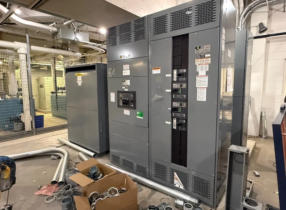
Start With What the Load Study Must Decide
A switchgear load study should answer specific planning questions, not simply total the connected equipment. Establish whether the project is a new facility, an expansion, a replacement, or a change in operating use; each can produce a different demand profile and equipment scope. Gather connected loads, expected operating schedules, motor starting characteristics, major non-linear loads, and planned future additions. Distinguish nameplate capacity from expected coincident demand, and document assumptions such as diversity and standby operation for review by the responsible electrical engineer. These inputs help the design team assess bus and feeder needs, metering, protective-device arrangements, and space for future circuits. Incomplete or optimistic assumptions can leave a new assembly poorly matched to actual operations.
Separate Normal, Peak, and Backup Operating Conditions
A single demand figure can conceal the conditions that drive equipment selection. Record normal operation, credible peak periods, seasonal variation, and any planned transfer between utility and standby sources. Identify which loads remain online during an outage, whether motors restart together, and whether load shedding or interlocking is part of the operating plan. For campuses and industrial plants, production cycles, process changes, and simultaneous equipment use may matter more than average monthly consumption. The study should show which values are measured, estimated, or forecast, with the date and operating state associated with each measurement. This distinction gives engineers and procurement teams a traceable basis for evaluating the proposed distribution arrangement without treating uncertain future demand as a guaranteed requirement.


Connect Load Findings to Equipment Requirements
Translate the study into a project-specific equipment schedule that the engineer can check before a quotation is finalized. Useful inputs include system voltage, phase and wire configuration, available fault-current information, main and feeder requirements, source arrangement, enclosure environment, metering needs, and anticipated spare or future provisions. Load results inform circuit and bus planning, but they do not independently establish interrupting ratings, protection settings, or a complete assembly design. Those decisions require coordination with the system study, utility information, applicable codes, and the project’s design authority. UL 891 applies to appropriately evaluated low-voltage switchboard assemblies; it is not a blanket certification for medium- or high-voltage equipment. Confirm the requested construction, evaluation, and labeling scope for the specific assembly.
Check Existing-System and Replacement Constraints
For replacement or retrofit planning, compare the proposed equipment requirements with verified site conditions rather than relying solely on old drawings. Document existing voltage and grounding, source and feeder arrangement, available fault-current data, conductor sizes and entry direction, room clearances, and the condition and function of connected loads. A load study may reveal that the facility’s demand has changed since the original switchgear was installed, but it cannot by itself establish that existing protection or conductors remain suitable. Coordinate field verification and engineering review before finalizing interfaces or reuse assumptions. This work can uncover limited working space, inaccessible cable routes, or incompatible connection locations early enough to address them in the scope, reducing the risk of redesign during installation.
Plan Timing Around Complete Information
A realistic procurement schedule depends on when design inputs are sufficiently settled, not just when a request for quote is issued. Provide the latest one-line diagram, load schedule, equipment specifications, site and environmental requirements, and a list of open engineering decisions. Mark revisions clearly and identify who can approve deviations or answer technical questions. Changes to the source arrangement, feeder count, enclosure, or control requirements can affect engineering, fabrication, and delivery coordination, so record them promptly and ask the manufacturer to confirm project-specific availability and timing. A U.S. manufacturer offering custom builds and short lead times still needs a defined scope to evaluate the schedule; do not treat an advertised general capability as a guaranteed delivery date for a particular project.
Coordinate Delivery With the Installation Site
Delivery planning belongs in the specification discussion because a finished assembly must reach its destination and installation area safely. Confirm receiving hours, truck access, unloading responsibility, dock or lift limitations, door and corridor clearances, floor loading considerations, and the route to the electrical room. Include shipment destination, site contact, packaging expectations, and any sequencing restrictions in procurement documents, then reconcile them with the equipment layout and installation plan. For facilities that must remain in service, coordinate outage windows, temporary arrangements, and required approvals with the owner and qualified electrical contractors. Nationwide shipping can support projects across the United States, but site access and handling conditions vary; verify the actual shipment plan and responsibilities rather than assuming standard delivery includes positioning or installation.