Define the Operating Sequence Before Selecting the Arrangement
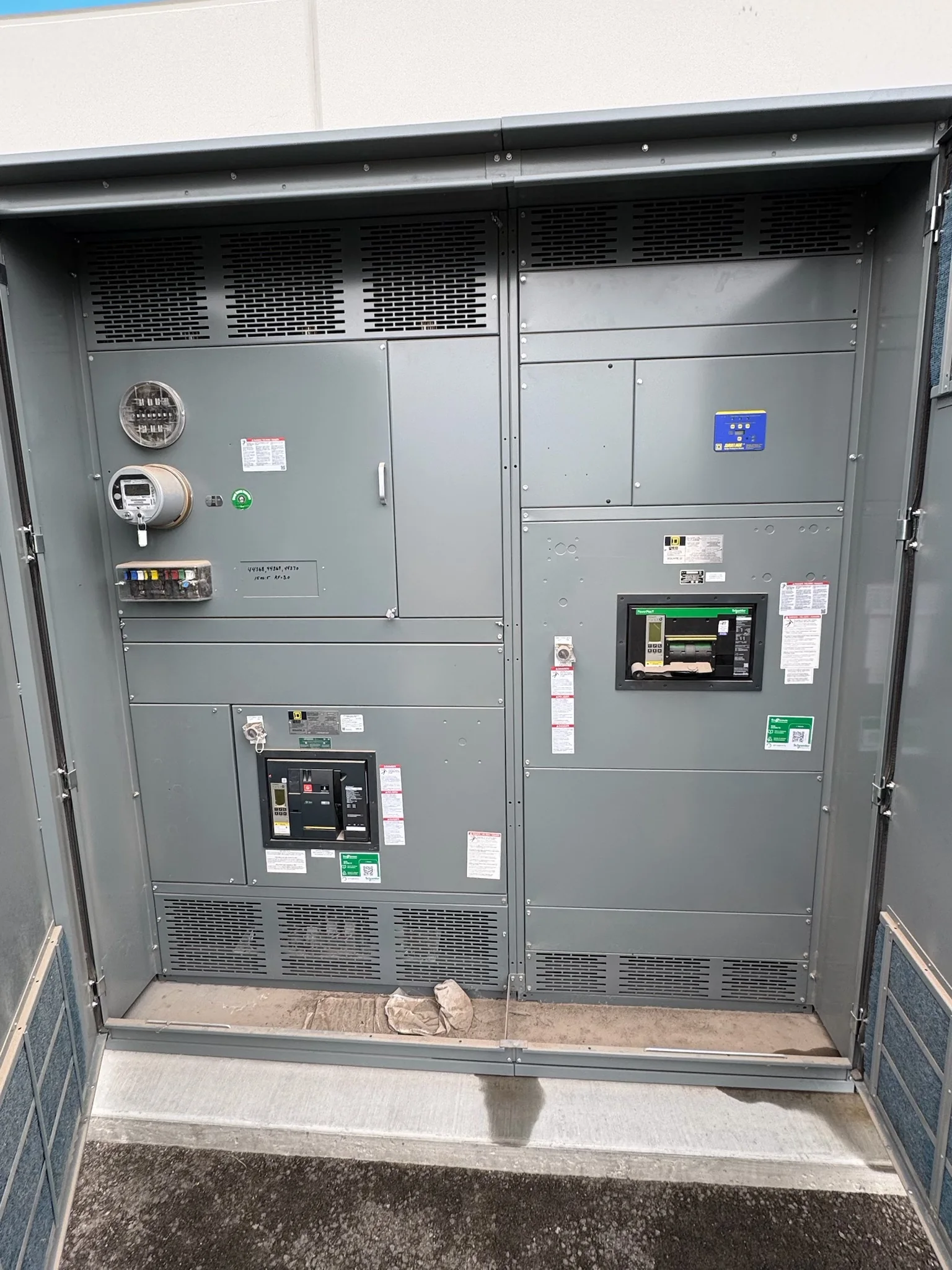
A main-tie-main (MTM) lineup divides a distribution system into two main sections connected by a tie breaker. Before requesting a quote, document the normal breaker positions, the conditions that permit transfer, and who or what initiates it. A manual scheme and an automatic transfer scheme have different control, interlocking, and operational requirements; neither should be assumed from the one-line diagram alone. Clarify whether the tie is normally open or normally closed, which sources may feed each section, and whether transfer is intended for maintenance, source failure, or both. These decisions affect equipment layout and control details. Review the proposed sequence with the electrical engineer and facility operators so the design reflects the actual operating procedure, not just a preferred lineup description.
Coordinate Sources, Loads, and Protection
An MTM arrangement does not, by itself, establish that sources can be paralleled or that either source can carry the entire facility. Confirm source characteristics, available fault current, load distribution, and the intended transfer conditions with the engineer of record. Protection settings and coordination should be evaluated for each permitted breaker configuration, because a tie operation can change fault-current contribution and protective-device relationships. Identify essential loads, loads that may be shed, and any equipment that must not experience an interruption. The procurement package should make these operating assumptions visible and request review of the applicable protection and control interfaces. Final ratings, interrupting capability, bus configuration, and protective-device selection depend on project conditions and require engineering confirmation; they should not be inferred from an MTM label.


Specify the Scope and Interfaces in the Quote Package
A useful request for quotation includes the current one-line diagram, equipment schedule, required ratings, project standards, and a written sequence of operation. State the number and arrangement of mains and tie breakers, metering needs, control-power source, alarm points, and any communications or remote-control interfaces. Identify which items are part of the switchgear scope and which are supplied by others, such as upstream transformers, protective relays, or building controls. Include required submittal formats, review milestones, inspection or test documentation, and labeling expectations. Missing interface details can create late design changes even when the basic lineup appears correct. A U.S. manufacturer can develop a project-specific proposal, but compatibility, applicable standards, exact ratings, and availability must be confirmed against the submitted requirements and the final design.
Check the Room, Access Route, and Installation Plan
Room conditions can determine whether a proposed lineup is practical long before equipment ships. Provide equipment-room dimensions, door and corridor clearances, floor and housekeeping-pad details, ceiling obstructions, cable-entry direction, and the intended working space. Confirm the delivery route from truck access to the final location, including loading-dock limits, elevators, turning areas, and any need to divide equipment into shipping sections. These constraints affect section arrangement, handling plans, and installation sequencing; discovering them after release can mean costly site work or rework. Coordinate structural support and conduit or busway approaches with the responsible trades. Have qualified project personnel verify access and installation requirements using the approved drawings and applicable codes; a preliminary footprint alone does not establish that the installation will fit or be compliant.
Plan Schedule Around Reviews, Release, and Readiness
Treat schedule as a series of project milestones rather than relying on an assumed standard lead time. Identify when the manufacturer needs approved drawings, frozen ratings, confirmed control interfaces, and authorization to proceed, then align those dates with the construction schedule. Clarify how many review cycles are planned and how revisions affect the release date. Site readiness matters too: receiving space, indoor storage conditions, rigging resources, foundations, and installation labor should be coordinated before shipment is scheduled. Ask for current project-specific timing and what information is still outstanding; short lead times may be available for some builds, but timing depends on scope, components, approvals, and production capacity. A realistic schedule also allows time for field installation, inspection, testing, and owner acceptance before the facility depends on the new lineup.
Coordinate Shipping, Turnover, and Future Operations
Nationwide shipping can support projects across the United States, but delivery planning still belongs in the project schedule. Confirm the receiving contact, delivery window, truck and unloading requirements, storage location, and responsibility for moving sections into the electrical room. Review packing and shipping documents against the approved equipment lineup, and report visible transit damage promptly through the agreed process. Before turnover, collect the approved drawings, final equipment documentation, operating sequence, maintenance information, and records required by the project. Train operators on the intended transfer logic and limits, including conditions that require escalation to qualified electrical personnel. Switching and maintenance procedures must account for hazards, required protective measures, and de-energized work practices; equipment delivery does not replace commissioning, site acceptance, or the facility’s responsibility for safe operation.