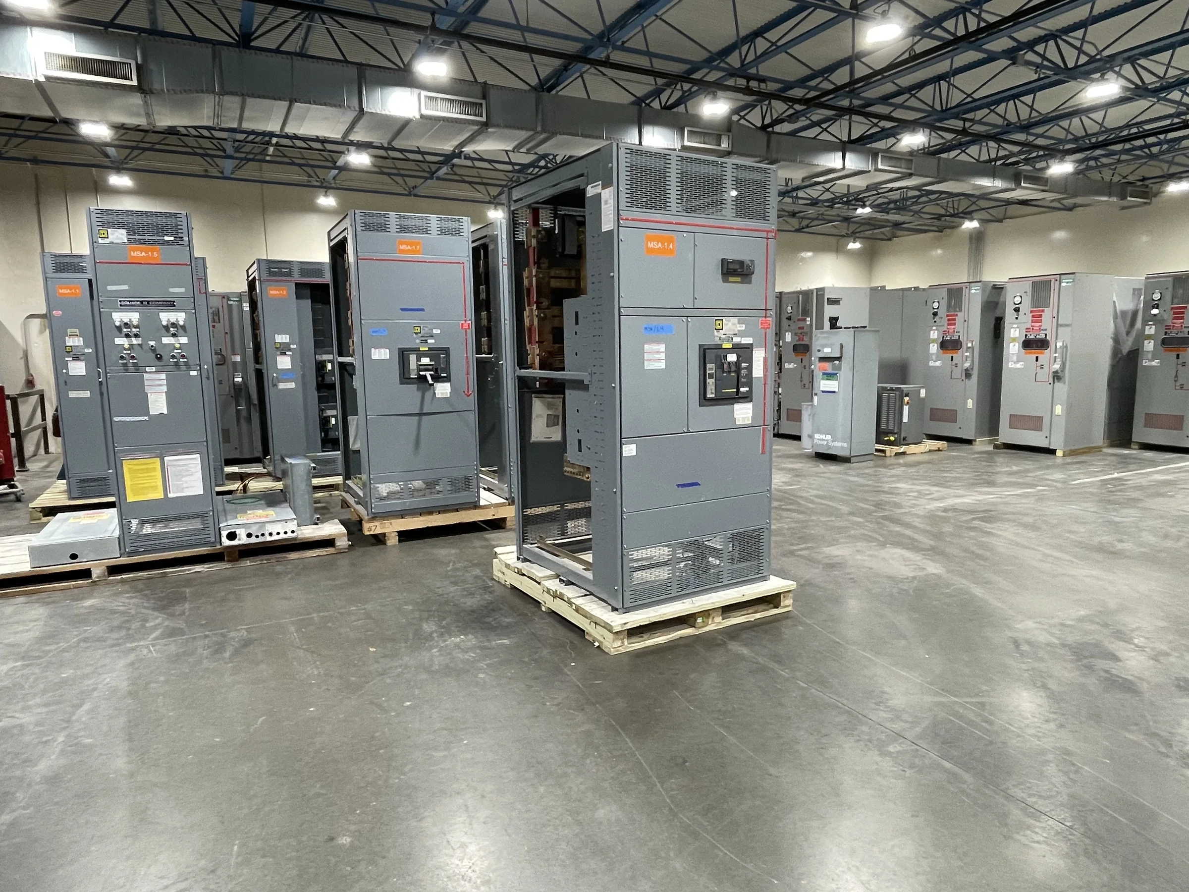
Plan Modernization Around the Operating Process
In an oil and gas facility, switchgear modernization has to account for the process loads it serves, not just the age of the lineup. Start by mapping existing feeders to pumps, compressors, heaters, control systems, utilities, and emergency loads, then identify which functions must remain available during each construction stage. This matters because an apparently straightforward replacement can interrupt a shared bus or remove power to equipment that operators depend on for safe, stable production. Gather one-line diagrams, load records, operating sequences, and known changes to the process before defining the new equipment. A U.S. manufacturer can build new distribution equipment around project requirements, but the design basis, interfaces, and transition plan need review by the facility’s engineering and operations teams.
Define the Electrical and Environmental Design Basis
Oil and gas locations can combine high continuous duty, motor-starting demands, outdoor exposure, dust, corrosive atmospheres, vibration, and temperature extremes. Which conditions apply varies by site area, so document them instead of assuming that one enclosure or construction approach fits the whole facility. Provide system voltage, available fault-current information, grounding arrangement, bus requirements, load schedules, protective-device preferences, and any applicable area-classification criteria for engineering review. These inputs affect equipment configuration and coordination with upstream and downstream systems; incomplete or outdated data can lead to a lineup that does not fit the intended application. Confirm applicable codes, standards, and owner requirements for the project. Any ratings, construction details, and standards applicability must be established for the specific design and evaluated equipment.


Resolve Interfaces Before Releasing the Build
Replacement switchgear must fit the electrical design and the physical room. Check existing lineup dimensions, aisle and working-space constraints, door and wall clearances, cable-entry direction, bus connections, conduit locations, grounding provisions, and access for installation and maintenance. Also confirm whether the project is a complete lineup replacement or a new assembly connected to retained equipment; that distinction changes the interface drawings, outage boundaries, and scope of field work. Cable lengths, termination space, and the condition of existing conductors can be easy to overlook until equipment arrives. Share verified room measurements, photographs, existing drawings, and connection details during specification review. Resolve discrepancies before fabrication, and document assumptions clearly, since field conditions and final compatibility require project-specific confirmation.
Coordinate Outages, Construction, and Delivery
A planned outage is often a narrow window between operating demands, permits, contractor availability, and process conditions. Build the procurement schedule around approved drawings, manufacturing, shipping, site access, receiving, installation, inspection, and commissioning—not an assumed equipment arrival date alone. Short lead times may be available depending on the design and current production requirements, but timing is project-specific and should be confirmed with the manufacturer. For remote plants, terminals, or compressor stations, coordinate delivery access, unloading capacity, storage protection, lifting routes, and weather exposure before shipment. A delivery that reaches the gate but cannot be unloaded or moved into the electrical room can jeopardize the outage plan. Keep operators, engineering, procurement, contractors, and the manufacturer aligned on milestones and schedule changes.
Prepare the Procurement Package and Review Submittals
A clear purchase specification helps procurement compare proposals on equivalent scope rather than headline price. Identify the required equipment function, system data, feeder arrangement, control and metering needs, interface limits, environmental conditions, documentation expectations, and any owner standards. Request a line-by-line response to exceptions and assumptions so engineering can see where the proposed assembly differs from the design basis. Review drawings for dimensions, access, cable terminations, bus interfaces, device functions, and labels before approving production. If low-voltage switchboard construction is specified, UL 891 may be relevant to an appropriately evaluated assembly; it is not a blanket certification for medium- or high-voltage equipment. Confirm the required evaluation, markings, and documentation for the specific product and application rather than treating a standard reference as automatic proof.
Plan Installation, Verification, and Long-Term Support
Before installation, align the approved equipment drawings with the contractor’s method, site safety requirements, outage authorization, and commissioning responsibilities. Electrical work must be performed by qualified personnel under applicable procedures, with equipment de-energized and verified safe before work begins; project-specific protective measures and approvals remain essential. Define who will inspect connections, confirm protective-device settings, verify control and interlock functions, and document results before the facility returns the equipment to service. Request operating and maintenance information, final drawings, device data, and a record of approved deviations as part of the handover package. These records help future teams troubleshoot changes without relying on outdated prints. New equipment can be configured for a modernization project, while final application suitability, interfaces, schedule, and delivery arrangements should be confirmed against site conditions.