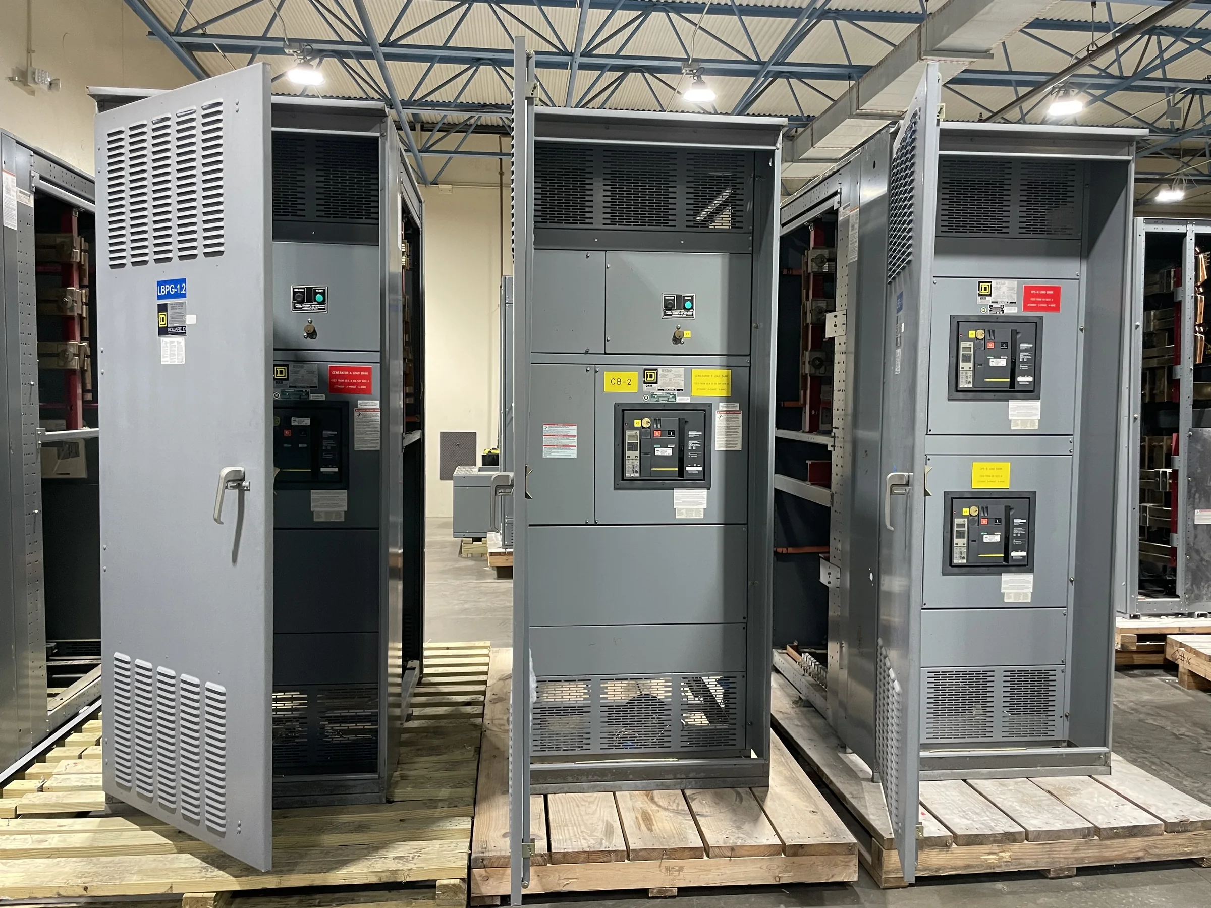
Define the Modernization Boundary Before Selecting Equipment
A power plant modernization can involve a complete distribution lineup, selected sections, or equipment serving a defined auxiliary load. Establishing that boundary early helps engineers avoid gaps between existing feeders, protective devices, and the new assembly. Document the source and destination of each circuit, normal and alternate power paths, load characteristics, available fault-current information, grounding arrangement, and required operating sequence. Identify interfaces with generators, transformers, station service systems, motor control centers, and plant control or protection systems. These details affect bus arrangement, compartment configuration, metering, control wiring, and equipment coordination. Treat the existing one-line diagram as a starting point, not proof of current field conditions. Confirm discrepancies through approved records and site assessment so the purchase specification describes the actual project, not an assumed replacement.
Build the Specification Around Plant Loads and Protection
Power plants depend on electrical distribution for equipment such as pumps, fans, compressors, lighting, and control-system support, but the mix differs by facility and operating mode. Specify which loads must remain available during startup, shutdown, normal generation, or an abnormal condition, and identify any required transfer or interlocking logic. Protection requirements should account for the system study, upstream and downstream devices, and the intended selective-coordination approach; do not select interrupting ratings or settings from a generic template. Provide available fault-current data, system voltage, frequency, conductor entry preferences, environmental conditions, and relevant owner standards. The manufacturer can use project information to develop equipment around the application, while final ratings, compatibility, and standards compliance remain subject to design review and the specified evaluation of the assembly.


Plan Replacement Work Around Outage and Continuity Needs
The installation window can be the hardest constraint in a plant switchgear project. A lineup may serve loads that cannot simply be interrupted together, so the owner and engineer should map required outages, temporary feeds if applicable, transfer steps, testing hold points, and restoration responsibilities before ordering. Verify which loads may be unavailable and for how long through the plant’s approved planning process; do not assume a temporary connection is feasible or acceptable. The equipment design may need to reflect phased installation, existing cable reach, termination access, and the sequence in which sections can be removed and installed. Early agreement on these constraints informs drawings and procurement decisions, reduces late field changes, and gives operations, maintenance, construction, and commissioning teams a shared basis for planning.
Verify Room Conditions, Interfaces, and Field Measurements
A replacement assembly must fit the plant’s electrical room and connect to existing infrastructure, not merely match a nominal lineup footprint. Record room access routes, doorway and overhead clearances, floor and anchorage conditions, working space, cable trench or overhead entry, and the location of nearby piping or other obstructions. Confirm whether existing bus, conduit, cable, grounding conductors, and control wiring can reach the proposed terminations, and document any constraints that affect section arrangement. Temperature, dust, moisture, corrosive exposure, and ventilation can also influence enclosure and installation decisions. Field dimensions and interface data should be checked against current drawings before design approval. Resolving these practical conditions early helps avoid equipment that cannot be moved into position or connected without unplanned plant modifications.
Align Submittals, Review Milestones, and Manufacturing Timing
A useful purchase package includes the project one-line, equipment schedule, applicable specifications, control and metering requirements, known interface drawings, and the planned review and approval process. Identify who will review the submittals and how comments will be consolidated, since unresolved changes to protection, wiring, or physical arrangement can affect manufacturing release. Discuss target dates and schedule constraints with the U.S. manufacturer at inquiry: custom configurations, engineering reviews, component availability, approvals, and shipping coordination all influence project timing. Short lead times may be offered, but a particular delivery date should be confirmed for the defined scope rather than assumed. Request a clear list of required customer inputs and decision dates, then track revisions so the approved equipment configuration stays aligned with the plant’s construction and outage plan.
Coordinate Delivery, Installation Records, and Acceptance
Nationwide shipping can support projects at plants in varied locations, but delivery planning still depends on site access and receiving arrangements. Confirm the delivery point, unloading responsibility, vehicle and crane access, storage conditions, packaging expectations, and any restrictions on receiving hours. Coordinate shipment with the construction schedule so equipment is protected and available when the installation area is ready, rather than exposed to unnecessary handling or unsuitable storage. Before field work, verify that the approved drawings and equipment identification match the delivered sections and intended connections. The project team should define required inspection, testing, documentation, and commissioning records in advance, including any owner or engineer acceptance criteria. For applicable low-voltage switchboard assemblies, address UL 891 evaluation requirements in the specification; it does not apply as a blanket certification to medium- or high-voltage equipment.