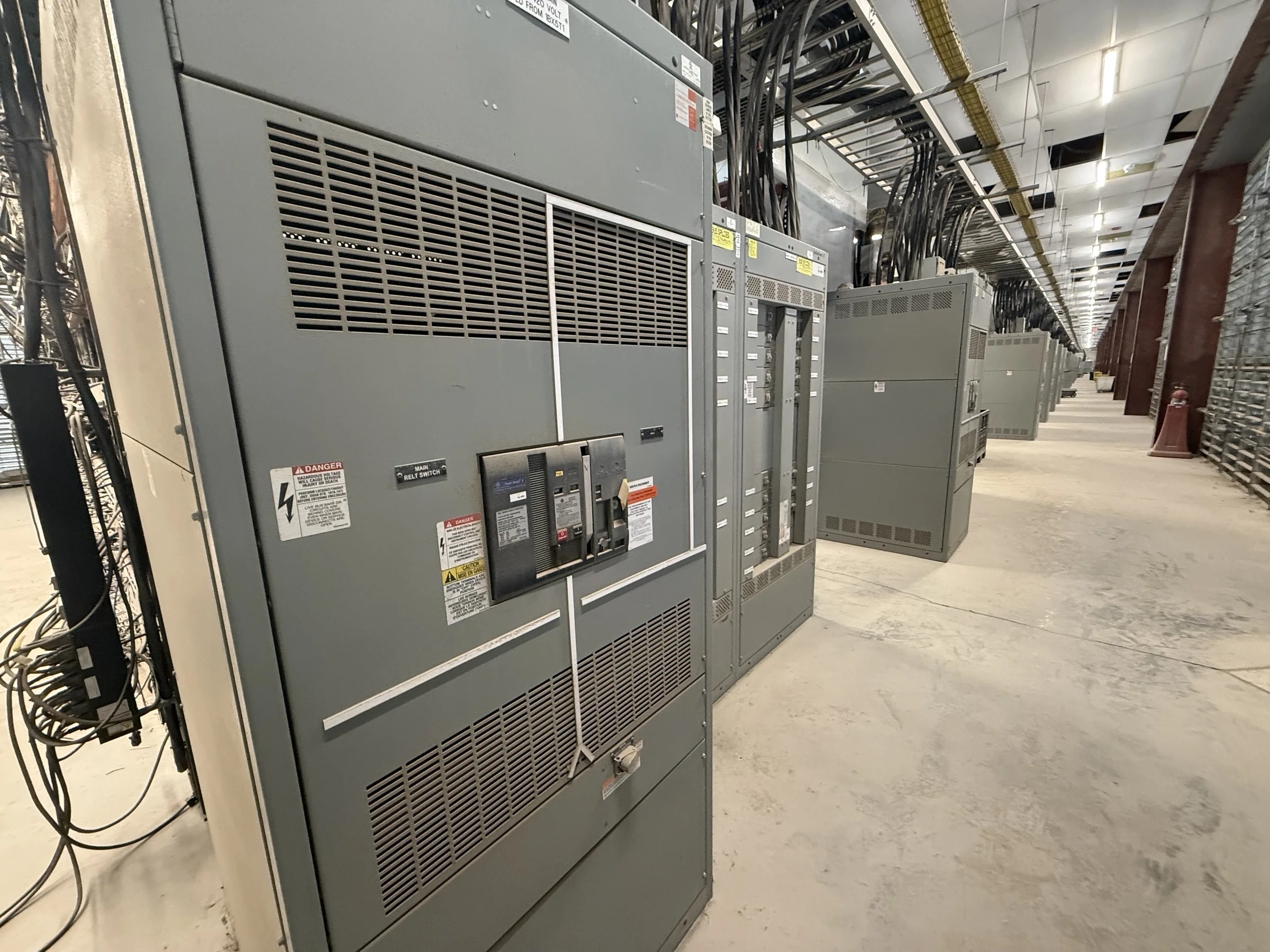
Modernization Begins With the Utility’s Operating Requirements
A utility modernization project should begin with the service conditions and operating needs the replacement equipment must meet—not with an assumed like-for-like lineup. Define nominal system voltage, available fault current, continuous load, switching duties, grounding method, and the expected operating sequence. Identify which circuits are essential, how sources are normally connected, and whether transfer, bus sectionalizing, or tie functions are required. These details influence equipment arrangement, interrupting capability, protection coordination, and the interfaces needed for safe operation. Existing drawings and nameplates provide a starting point, but field conditions and current studies may reveal changes since the original installation. A manufacturer can use the project criteria to develop a new-equipment proposal; final ratings, configuration, and standards applicability must be confirmed for the specific system.
Document the Existing Installation Before Selecting New Gear
Reliable replacement planning depends on a usable record of the installation. Gather one-line diagrams, elementary and wiring diagrams, equipment schedules, protection settings, cable schedules, control schematics, and available short-circuit and coordination studies. Record lineup dimensions, bus arrangement, cable entry direction, conductor types and sizes, conduit locations, grounding connections, and the position of adjacent equipment. Note obsolete relays, unusual interlocks, metering circuits, communications links, and interfaces to station batteries or supervisory controls. Missing or conflicting documentation can delay engineering review and create commissioning questions, especially when a new assembly must connect to legacy circuits. A site survey and drawing review can identify information gaps early. Treat verified field measurements as project inputs, not as a substitute for approved design and installation documents.


Coordinate Protection, Controls, and Utility Interfaces
Modernization is more than replacing a metal enclosure: protection and control functions must work with the utility’s wider operating scheme. Establish which devices trip, close, alarm, meter, or communicate with remote systems, and define the required contact logic and signal interfaces. Confirm whether existing protective relays will be retained, replaced, or coordinated with new equipment, then have qualified engineering personnel review settings against current system studies and operating practices. Check instrument-transformer requirements, control-power sources, wiring terminals, communications protocols, and any utility-specific point lists before approving drawings. A mismatch can leave operators without expected indication or prevent equipment from responding correctly to a fault or switching command. Clarify responsibility for interface design, settings files, testing, and final records so each party knows what must be verified before service.
Plan Replacement Around Outage and Site Constraints
For a utility, the outage window may be the hardest constraint in the project. Determine how loads will be supported during construction, which circuits can be interrupted, what temporary arrangements are permissible, and who authorizes switching and clearances. Construction sequencing should account for removal, anchoring, cable work, terminations, inspections, testing, and restoration—not just the physical placement of the new lineup. Confirm access routes, door and ceiling clearances, lifting points, floor capacity, equipment-room ventilation, housekeeping pads, and restrictions on staging. Existing conductors may not reach new terminals, while cable bends or conduit entries may conflict with a revised enclosure layout. Resolve these issues during design review where possible. All work must follow approved utility procedures, applicable codes, and a properly de-energized, verified safe work condition.
Review Drawings, Submittals, and Scope Before Release
A complete procurement package helps align the manufacturer, utility engineering team, installer, and commissioning personnel before fabrication. Specify the required assembly type and ratings, arrangement, access needs, finish, bus and cable interfaces, protective devices, control features, metering, labeling, and documentation deliverables. Request project drawings for review, including general arrangement, one-line representation, schematics, connection details, and foundation or anchoring information as applicable. Identify which party supplies cables, external relays, communication equipment, field testing, and settings coordination; ambiguous scope can become a costly issue at installation. Confirm applicable standards and any requested evaluation or marking for the particular equipment. UL 891 applies to appropriately evaluated low-voltage switchboard assemblies, not automatically to medium- or high-voltage gear. Approve deviations and drawing revisions through documented project review.
Coordinate Manufacturing, Delivery, and Commissioning Records
Discuss schedule and delivery requirements with the U.S. manufacturer early, sharing the required in-service date, approval milestones, site access limits, and any phased shipment needs. Custom configurations and component availability can affect the production plan, so obtain a project-specific schedule rather than relying on an assumed lead time. Nationwide shipping does not remove the need to plan receiving: verify unloading capacity, delivery access, weather protection, storage conditions, and responsibility for moving sections into the electrical room. Before energization, qualified personnel should complete the specified inspections and functional checks under approved procedures, then resolve discrepancies and document results. Closeout records should include approved final drawings, equipment and device data, settings documentation where applicable, test records, and operating instructions. A disciplined handoff gives utility staff the information needed to operate and maintain the new installation.