Modernization Starts With the Existing System
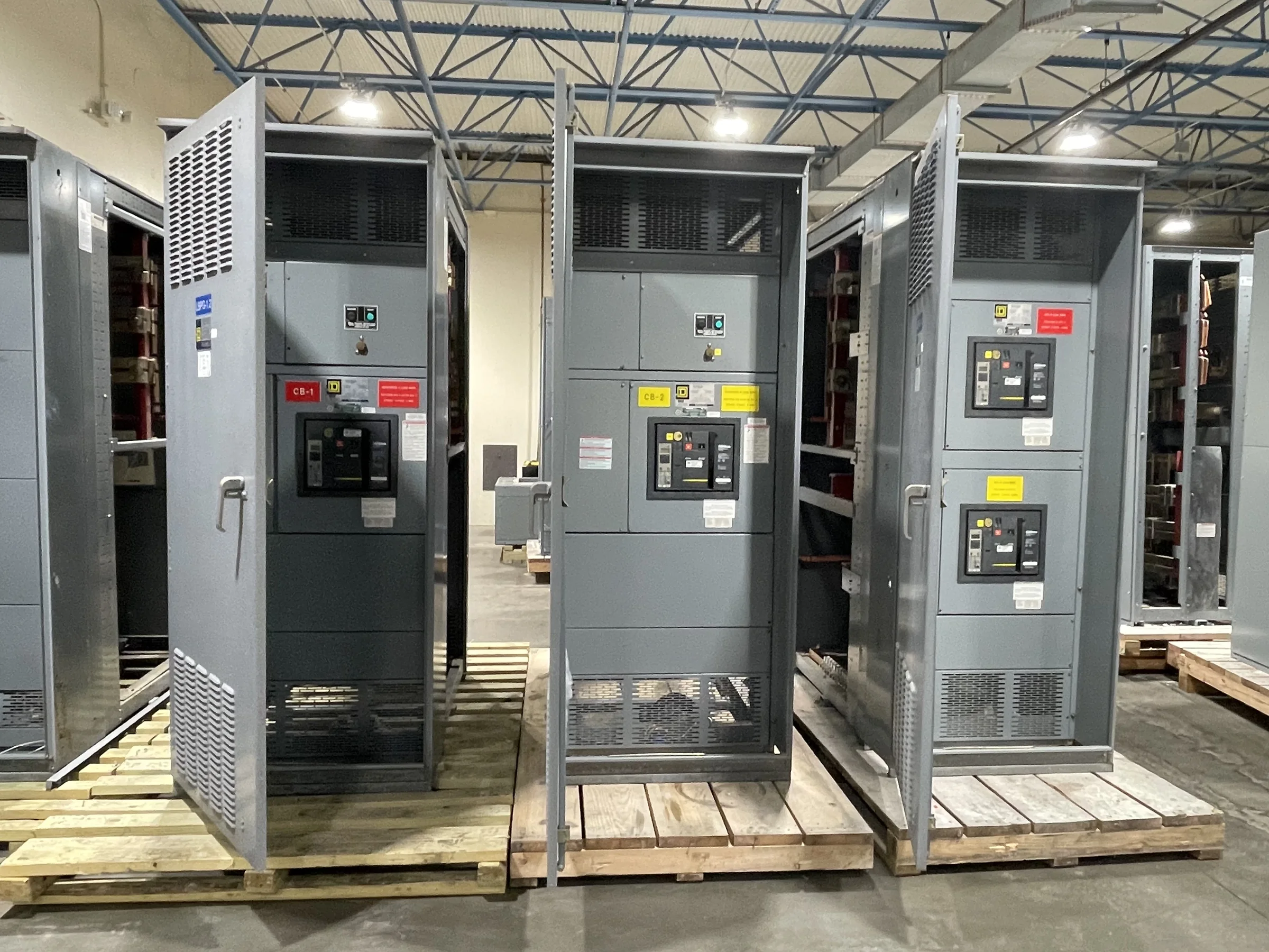
In Alvin, modernization planning should begin with the electrical distribution equipment already serving the facility, not with a presumed replacement lineup. Document the switchgear or switchboard manufacturer and model, nameplate data, one-line diagram, protective-device settings, available fault-current information, and connected loads. Compare those records with a field survey: equipment dimensions, bus arrangement, cable entry points, conduit locations, grounding, access clearances, and signs of heat or corrosion. This comparison can expose a critical constraint early, such as feeders that cannot reach a proposed new section or a footprint that blocks maintenance access. Existing gear may be a reference for a new design, but matching appearance alone does not establish electrical or mechanical compatibility. Confirm requirements for the specific application with the responsible engineer.
Define Electrical Requirements Before Requesting a Quote
A useful request for quotation gives the manufacturer enough information to develop a project-specific proposal without treating unknowns as settled. Identify system voltage, phase, frequency, service configuration, intended continuous loads, available fault-current data, and the functions required of each feeder or main device. Include the one-line diagram and note whether the project requires metering, ground-fault protection, transfer provisions, special enclosures, or coordination with existing equipment. These details matter because interrupting ratings, bus ratings, device selection, and physical arrangement depend on the actual system and applicable project requirements. If data is missing, flag it for engineering review rather than substituting an assumption. For low-voltage switchboard assemblies, discuss whether UL 891 evaluation applies to the proposed assembly; it is not a blanket qualification for medium- or high-voltage gear.


Check Interfaces, Protection, and Replacement Boundaries
A replacement lineup must work as part of the distribution system, not merely fit within the electrical room. Review how mains, feeders, transformers, generators, transfer equipment, and downstream panels interact, then establish the intended protection and coordination approach with the project engineer. Confirm cable landing space, conductor routing, neutral and grounding arrangements, control wiring, communications, and any required connection to building monitoring systems. An interface overlooked during design can force field changes or delay return to service, especially when existing conductors or control circuits are being retained. Do not assume that a new section can connect directly to legacy bus or devices because dimensions appear similar. Document the boundary between new and existing equipment, identify what will be removed or reused, and verify every compatibility decision against project drawings and equipment data.
Plan Outage Windows and Work Sequencing
Schedule discussions should address the full path from approved submittals to installation readiness, rather than focusing only on fabrication duration. Custom builds and short lead times may be available, but timing depends on the approved design, component selection, project scope, and current availability; obtain a project-specific schedule from the manufacturer. Alvin facilities should coordinate planned outages with operations, utility requirements, contractors, and any affected tenants or production teams. Identify whether temporary power, staged installation, or phased cutover is part of the engineer’s plan, and who is responsible for each interface. A delivery date is useful only when the site can receive, store, and move the equipment to its final location. Confirm milestones, review periods, shipping assumptions, and schedule risks in writing, and never treat energized work as an acceptable substitute for proper de-energization.
Coordinate Delivery and Room Access in Alvin
Delivery planning should be based on the actual route into the facility, not just the street address. For an Alvin project, confirm site-specific truck access, receiving hours, gate or security procedures, unloading responsibility, turning space, and any restrictions on delivery vehicles. Then measure the route from the receiving point to the electrical room, including door openings, corridors, ramps, overhead obstructions, and floor conditions. A lineup that clears the entrance may still be difficult to position if the route includes a narrow turn or limited staging area. Share these constraints before the equipment arrangement is finalized so the project team can review shipping sections, handling provisions, and installation sequence. Nationwide shipping can support projects in the area, but carrier arrangements, packaging, unloading, and final placement must be confirmed for each shipment.
Review Submittals and Prepare for Commissioning
Before release for construction, review the proposed lineup against the approved one-line diagram, equipment schedule, room layout, and project specifications. Check device functions, ratings, enclosure requirements, connection locations, control schematics, metering details, and the division between factory wiring and field connections. Make sure drawing revisions are tracked and that the electrical contractor, engineer, facility representative, and manufacturer are working from the same approved set. This review matters because a discrepancy discovered after fabrication can affect fit, interfaces, or the planned outage. Also establish what inspection, testing, labeling, and turnover records the project requires; do not assume a particular test, certification, or listing without confirming the actual scope. Before energization, qualified personnel should complete the required installation checks and commissioning activities under the project’s approved safety procedures.