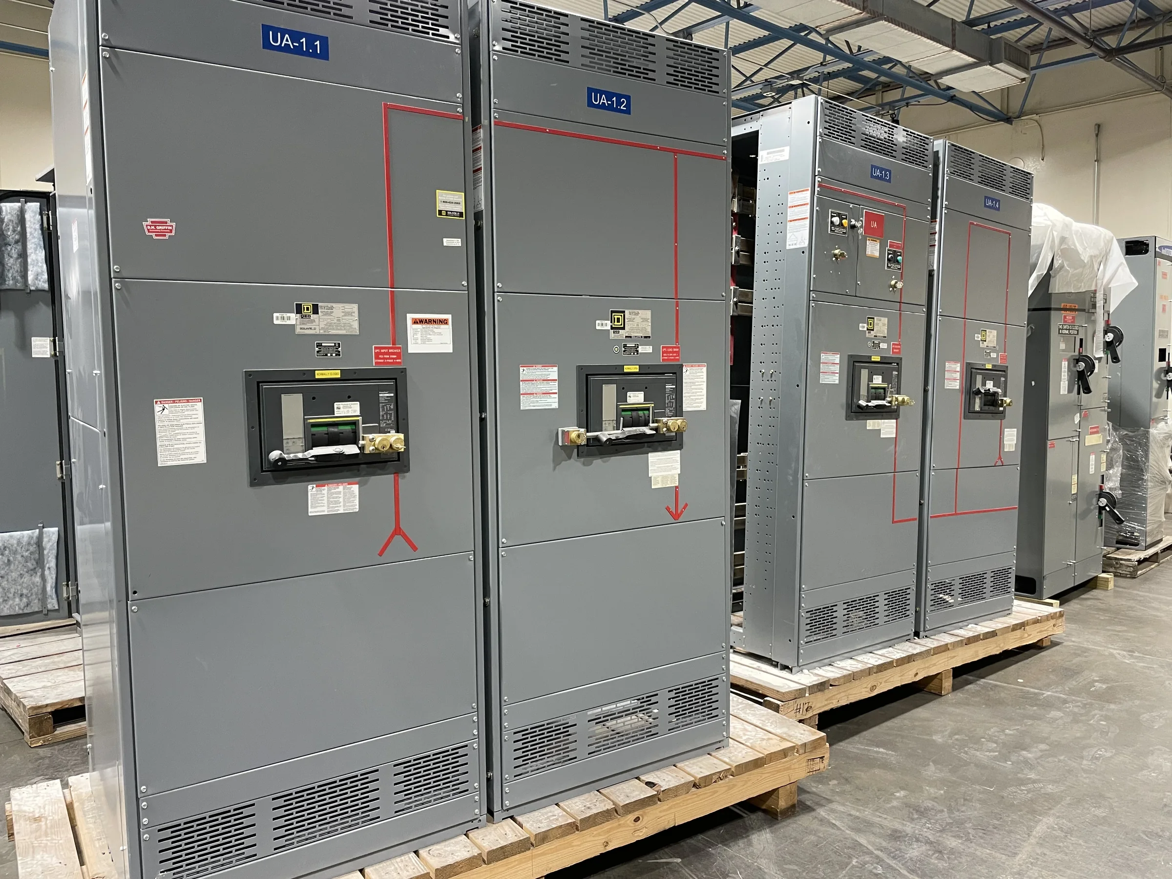
Define the Modernization Scope Before Selecting Equipment
In Tomball, a switchgear modernization can mean replacing an aging lineup, changing the distribution arrangement, or supplying new equipment for a facility expansion. Those are different scopes, and the distinction affects both design and purchasing. Start by documenting the existing one-line diagram, system voltage, available fault-current information, feeder destinations, protective-device data, and the reason for the project. Identify equipment that must remain in service and interfaces that cannot move, such as transformers, generators, transfer equipment, or downstream panels. This record helps the manufacturer assess what the new assembly must connect to without assuming the existing lineup can be duplicated. Confirmed scope also helps the owner compare bids on equivalent equipment and identify gaps before drawings, pricing, or a replacement plan are approved.
Turn Field Conditions Into Actionable Specifications
Existing switchgear rooms often impose constraints that are absent from a one-line diagram. Before finalizing a specification, verify room dimensions, ceiling height, access routes, door clearances, floor condition, conduit entry locations, and the space needed to position and join sections. In an operating Tomball facility, an entrance that works for routine maintenance may not accommodate delivery of a large assembly. Photographs and measured sketches can reveal these conflicts early, but should not replace field verification where dimensions affect fit. Record environmental conditions and site requirements, including indoor or outdoor placement and any exposure to dust, moisture, or corrosive substances. These details matter because enclosure, construction, shipping splits, and installation planning depend on the actual site—not simply the equipment’s electrical ratings.


Coordinate Protection, Interrupting Ratings, and Interfaces
Modernization decisions must account for how protective devices coordinate with the source and downstream loads. Provide available fault-current and system-grounding information, upstream device data, and feeder loads so the proposed equipment can be evaluated for the intended application. Interrupting and short-circuit ratings, bus arrangements, metering, and control interfaces must be confirmed against project conditions; they should not be inferred from the existing gear’s nameplate alone. Where generators, utility services, transfer schemes, or sensitive process loads are involved, document operating modes and required interlocks. This is especially important when a facility expects to expand or change its source configuration. The manufacturer can build to an approved project specification, while the responsible engineer verifies system studies, protection settings, and code applicability.
Plan Replacement Around Outage and Installation Constraints
A new lineup may be designed around a planned outage, but equipment delivery does not by itself determine when a facility can be switched over. Establish who will develop the outage sequence, approve the work plan, isolate and verify the existing equipment, and commission the replacement. Electrical work must be performed by qualified personnel under the facility’s safety procedures; required de-energization and verification cannot be treated as optional to meet a schedule. For Tomball sites with active production, building operations, or limited staging space, coordinate the proposed delivery window with receiving access, rigging arrangements, laydown area, and weather exposure. Discuss timing with the manufacturer early, but treat lead time and ship date as project-specific until confirmed in the quote and order documents.
Review Drawings, Submittals, and Acceptance Requirements
A complete procurement package makes it easier to confirm that the offered equipment matches the project before fabrication. Request drawings and submittals that show dimensions, lineup arrangement, bus and feeder configuration, device schedules, metering, control wiring, and connection points as applicable. Compare these documents with the one-line diagram and installation drawings, then return consolidated comments through the project’s approval process. Identify required labeling, spare provisions, accessories, documentation, and any inspection or testing requirements in the purchase specification rather than assuming they are included. UL 891 applies to appropriately evaluated low-voltage switchboard assemblies; it is not a blanket certification for medium- or high-voltage equipment, and a product’s labeling must be confirmed for the specific assembly. Clear review responsibilities reduce late changes and acceptance disputes.
Coordinate Delivery and Replacement With the Project Team
As a U.S. manufacturer offering custom-built equipment, American components, short lead times, and nationwide shipping, the supplier can discuss a configuration and delivery plan against the project’s actual requirements. Confirm the quoted scope, approved drawings, delivery terms, shipment dimensions, receiving hours, unloading responsibility, and any restrictions on truck access before placing the order. For a Tomball project, local road access, gate procedures, construction traffic, and available staging can affect the practical delivery plan even when the ship-to address is straightforward. Align the shipment with site readiness and the installation contractor’s schedule; storing equipment outdoors or moving it before the room is prepared can create avoidable handling and condition risks. Final availability, timing, standards, and compatibility remain subject to project-specific review and written confirmation.