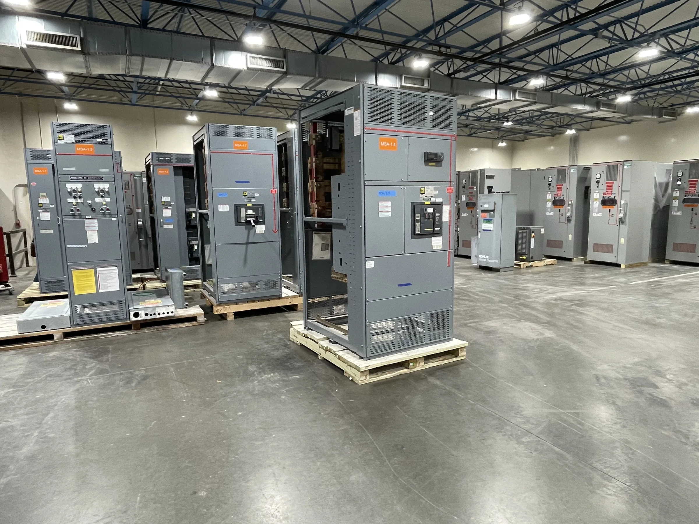
Define the Work Boundary Before Selecting Equipment
A phased replacement begins with a clear boundary between equipment that will remain in service and equipment included in the new installation. Document the existing lineup, connected loads, normal and alternate sources, tie breakers, protective devices, and any shared control or metering circuits. This matters because a new section that fits the available footprint may still fail to coordinate with retained gear or serve the intended operating arrangement. Gather nameplate data, current one-lines, elementary diagrams, and available fault-current information; flag missing or conflicting records for field verification. Identify which functions must remain available during each stage, including life-safety, process, and essential building loads. These decisions establish a usable basis for manufacturer discussions without assuming that existing ratings or construction can be carried forward unchanged.
Turn Existing Conditions Into a Project-Specific Specification
A quotation request should describe the electrical duty and the physical interface, not just the desired lineup length. Provide system voltage, phase and wire arrangement, available fault-current data, main and feeder requirements, grounding method, enclosure environment, cable entry direction, and required metering, controls, or communications. Include breaker frame and trip requirements where known, but have the design team confirm protection and coordination against the study and applicable codes. For retained equipment, record bus arrangement, compartment dimensions, connection details, and manufacturer identification; photographs help, but do not replace verified measurements. State which information is confirmed, assumed, or pending. This distinction helps the U.S. manufacturer identify open engineering questions early, reduces avoidable quote revisions, and keeps a proposed configuration from being mistaken for a guaranteed fit or listing.


Build the Sequence Around Loads and Switching Boundaries
Break the work into stages that correspond to real electrical boundaries, such as a source section, a distribution section, or a defined group of feeders. For each stage, show the equipment to be isolated, loads affected, temporary supply needs, and the intended operating configuration before and after the cutover. A load list alone is not enough: shared controls, transfer schemes, protective interlocks, and downstream backfeed paths can complicate an apparently simple division. Have the responsible engineer and facility operations team review each sequence, including contingency actions if testing or restoration takes longer than planned. This matters because an equipment delivery plan cannot by itself establish a safe switching plan or preserve continuity. All work must follow approved procedures, with equipment de-energized and absence of voltage verified before work begins.
Coordinate Procurement, Engineering, and Release Dates
Phased projects often require equipment information before every site detail is settled, so assign owners and due dates to each open item. Track approved drawings, breaker and accessory selections, control schematics, cable schedules, finish or enclosure requirements, and any interface dimensions needed for fabrication. Agree on the review and approval path before ordering; late changes to bus connections, feeder arrangements, or controls can affect design and procurement. Ask the manufacturer to identify what is required to proceed, what remains subject to confirmation, and what changes may alter the commercial proposal or schedule. Short lead times may be an offering, but actual timing depends on the approved scope, component availability, engineering review, and production conditions. Put the required delivery window and any phased shipment expectations in the purchase documents, then confirm them as the project advances.
Plan the Site, Removal, and Delivery Route
Measure the full route from receiving point to the electrical room, including dock openings, corridors, turns, elevator or crane access, floor loading limits, door clearances, and overhead obstructions. Compare the proposed shipping sections and handling method with those constraints before approving equipment construction; a lineup can meet electrical needs yet be impossible to move through the available path as planned. Confirm where each shipment will be staged, how packaging will be protected, and whether the site can accept deliveries in the intended sequence. Coordinate unloading, rigging, access control, and storage with facility operations and the carrier, and identify who verifies shipment condition and completeness. Nationwide shipping does not remove local access or receiving constraints. Clear delivery instructions and a realistic staging plan reduce damage risk and avoid equipment arriving before the site is ready.
Close the Design and Turnover Gaps Before Each Phase
Before a stage is released for installation, reconcile the latest approved one-line and wiring drawings with field conditions, interface points, feeder terminations, protection settings responsibility, and control logic. Identify tests, inspections, permits, shutdown approvals, and acceptance records required by the project team and authorities; responsibilities depend on the scope and jurisdiction. For low-voltage switchboard assemblies, UL 891 may be relevant when the assembly is appropriately evaluated, but it does not apply as a blanket certification to medium- or high-voltage equipment, and a manufacturer offering alone does not establish a product’s label. Confirm applicable evaluation and documentation for the specified assembly. After each phase, update as-built drawings, equipment identifiers, settings records, and operating procedures before moving to the next boundary. This turnover preserves accurate records and supports safe, maintainable operation.