Define the Study Boundary Before Specifying Equipment
A protection coordination study evaluates how selected protective devices respond to faults and overloads across a defined electrical system. Before requesting new switchgear, establish which sources, transformers, buses, feeders, motors, and downstream devices belong in the model. Leaving out a utility contribution, generator, tie breaker, or existing feeder can change calculated fault current and coordination conclusions. Gather one-line diagrams, available fault-current information, transformer data, conductor details, protective-device settings, and relevant equipment records; mark uncertain or outdated information for verification. For procurement, the study boundary also identifies which devices must be supplied, retained, or replaced. Give the manufacturer the intended system arrangement and project documents early, while treating final ratings, device selection, and compatibility as engineering decisions that depend on verified project conditions.
Coordinate Fault Ratings, Bus Arrangement, and Device Selection
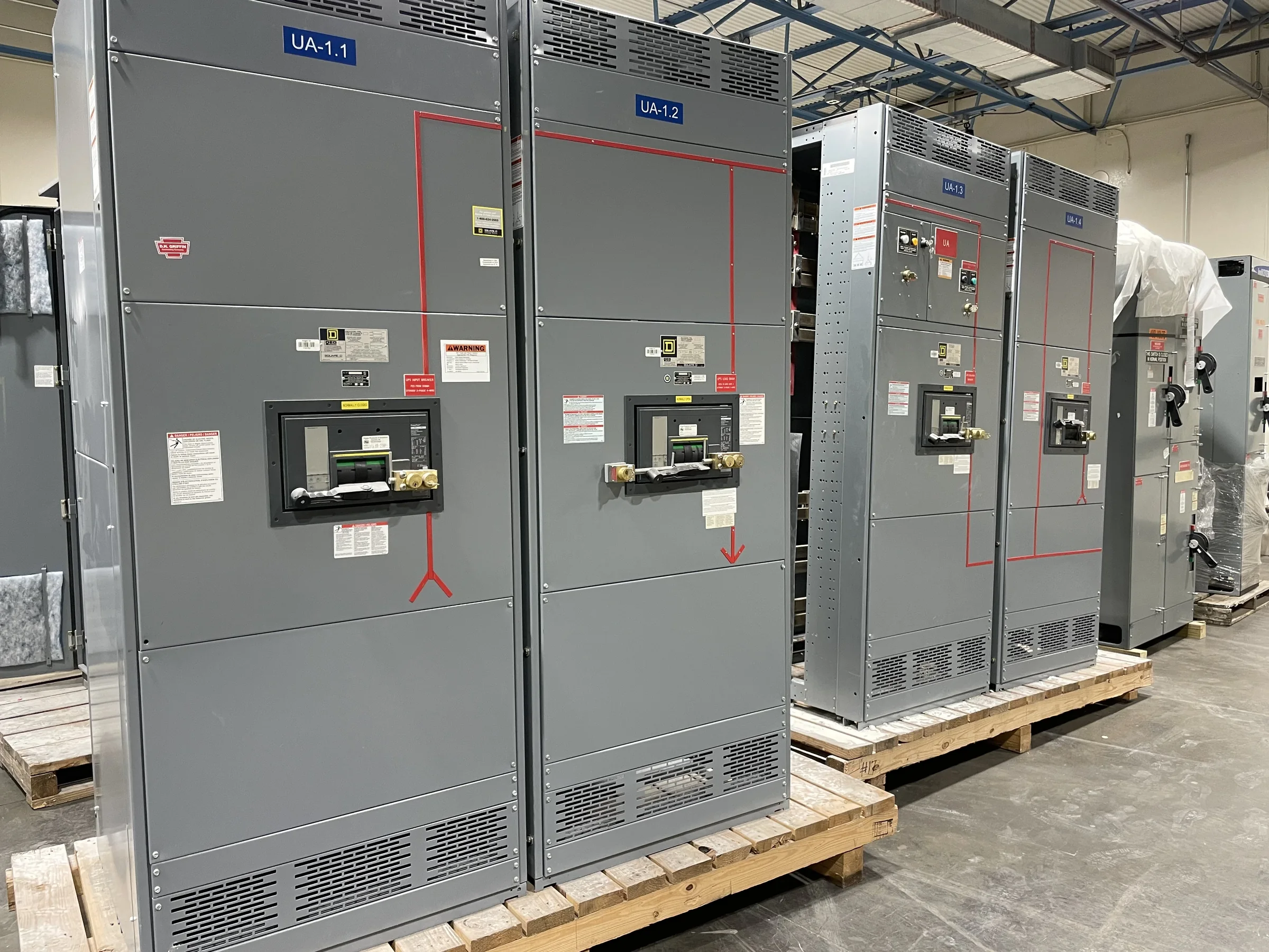
Available fault current at each switchgear location affects interrupting and withstand requirements, while device operating characteristics affect which protective device responds first. The study should use project-specific source and transformer information rather than assume a standard fault level or a familiar lineup will suit the application. Describe the proposed bus configuration, incoming sources, ties, feeder functions, and expected operating modes so the engineer can evaluate relevant fault paths. When planning replacement equipment, provide existing nameplate data, drawings, and device information where available; physical fit alone does not establish electrical suitability. Clarify whether new assemblies, breakers, trip units, or other components are being considered, and keep final ratings and device compatibility subject to engineering review, applicable requirements, and the evaluated assembly design.


Review Selective Coordination Against Operating Priorities
Coordination decisions balance fault isolation, equipment protection, and continuity of service; they are not simply a matter of making every upstream device slower. A facility may need particular attention to life-safety loads, process-critical feeders, emergency sources, or branches where an unnecessary shutdown carries substantial operational consequences. Identify those priorities in the study request and explain normal and alternate operating arrangements. The engineer can then assess time-current relationships and device settings for the documented scenarios, including where selectivity may be limited. Avoid assuming that a coordination objective can be achieved for every fault level or operating condition without affecting protection. Document accepted tradeoffs and any settings or equipment choices that require owner approval, so procurement decisions reflect real operating needs rather than an unverified promise of uninterrupted service.
Plan Field Data Collection and Installation Constraints
A useful study depends on accurate field information, but obtaining it at an operating facility requires careful planning. Existing labels may be missing, panel schedules outdated, or installed devices different from the records; each discrepancy can undermine model accuracy or delay design decisions. Arrange qualified personnel, approved site access, and required safety controls for inspections and data collection. Electrical work must follow applicable procedures, and equipment must be de-energized when required; a study schedule is not a reason to bypass safe work practices. Record equipment identifiers, physical conditions, cable and transformer data, and any uncertainty that needs follow-up. Separately document room access, working clearances, doorways, rigging routes, floor or loading limitations, and shutdown windows, since these can influence lineup configuration, replacement planning, and delivery coordination.
Use Study Deliverables to Support Purchasing Decisions
Before placing an equipment order, align the study deliverables with the project’s design and procurement milestones. Useful records may include the modeled one-line diagram, documented assumptions, fault-current results, device coordination plots, proposed settings, identified exceptions, and a list of information still requiring confirmation. Agree on who supplies utility data, verifies field conditions, reviews the study, and approves settings; unclear ownership often creates late revisions. A U.S. manufacturer can use the project’s approved drawings, electrical requirements, and installation constraints to discuss a new custom build and American-component options. Short lead times and nationwide shipping are offerings, not substitutes for confirming scope, design release, component availability, or freight arrangements. Confirm delivery expectations for the specific order, including receiving access and any site restrictions, before treating dates as established.
Verify Settings, Documentation, and Closeout Responsibilities
Study recommendations only help when they reach the people responsible for commissioning and future maintenance. Identify how approved settings will be transferred to the installation team, checked against furnished devices, recorded in equipment documentation, and controlled after energization. Changes to sources, transformers, conductor routes, breaker models, or operating modes can invalidate earlier results and should trigger engineering review rather than informal adjustment. Include updated one-line diagrams and final device information in the closeout record, with clear revision dates and responsibility for maintaining the documents. For new low-voltage switchboard assemblies, UL 891 applies only where the assembly is appropriately evaluated; it is not a blanket certification for medium- or high-voltage equipment. Confirm project-specific listing, standards, and evaluation requirements with the responsible design and procurement teams before finalizing the specification.