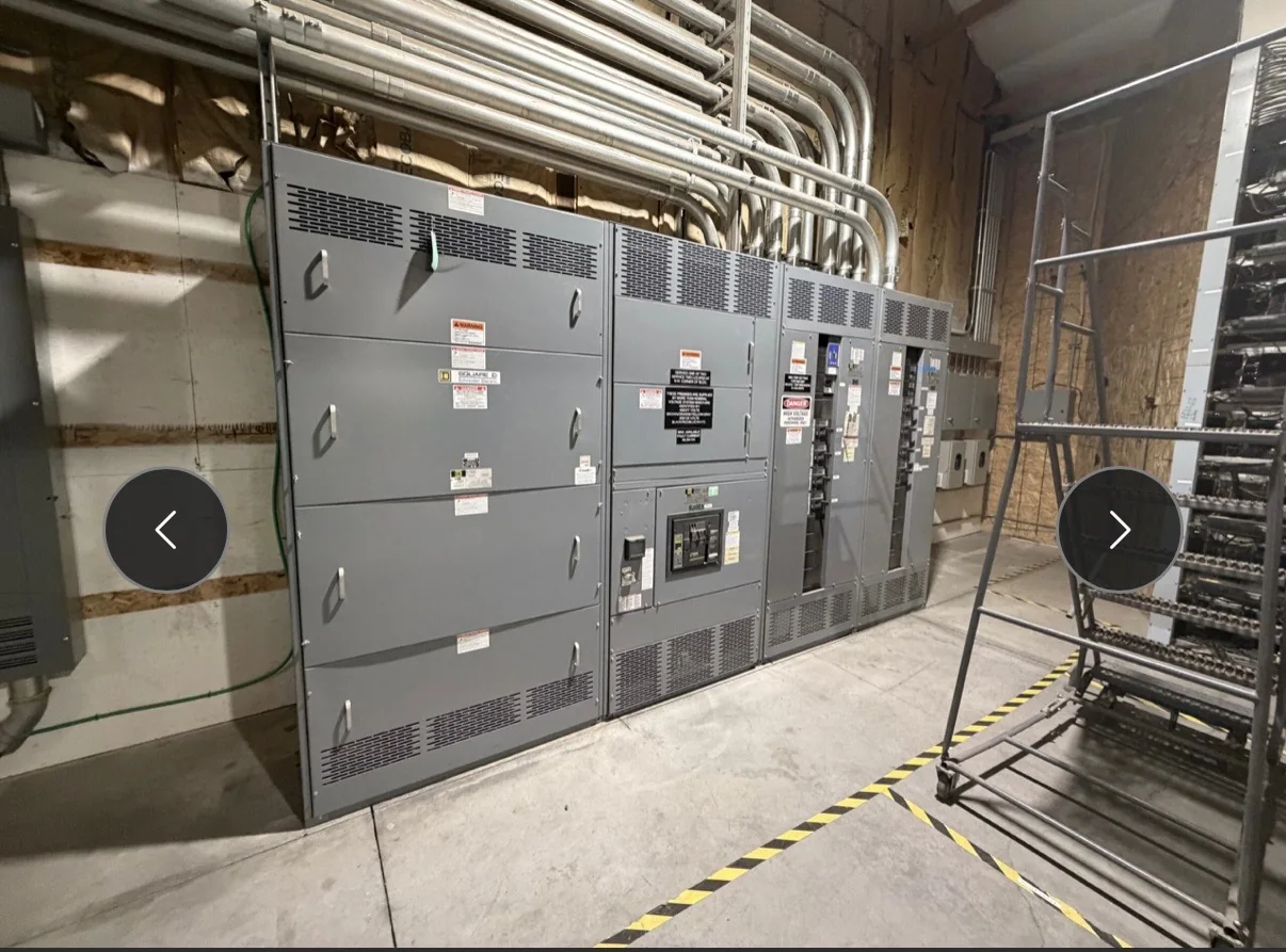
Define the Protection Objective Before Selecting Relays
Protective relaying should begin with the system problem the equipment must address, not a relay model or feature list. Identify the circuits, transformers, generators, motors, or bus sections to be protected, then establish which abnormal conditions require detection and what equipment should trip. This clarifies the intended protection zones and helps prevent gaps or unnecessary overlap. Coordination with upstream and downstream devices matters: a fault should be isolated as selectively as the system design permits, while still clearing faults within the required time. Gather the one-line diagram, available fault-current information, grounding approach, and existing protection settings early. Those records give the manufacturer and project engineer a sound basis for defining the switchgear arrangement and relay functions. Final application decisions depend on the system study and project requirements.
Match Relay Functions to the Switchgear and System
A relay’s listed functions must suit the protected equipment, instrument transformers, trip circuits, and operating scheme. Overcurrent elements, for example, may be part of a feeder protection plan, but their settings depend on fault levels, load, conductor and equipment limits, and coordination with other devices. Differential, ground-fault, voltage, frequency, or directional functions may be considered where the system conditions and protection philosophy call for them; none should be added simply because they are available. Confirm whether relays are standalone devices or integrated into a control and metering arrangement, and identify required communications or indication at the outset. These choices affect panel space, wiring, control power, testing, and documentation. The final functions and settings should be reviewed by the responsible protection engineer for the actual installation.


Resolve Instrument Transformer and Trip-Circuit Details
Protection performance depends on the signals and trip path between the power system and the relay. Current and voltage transformer ratios, accuracy, burden, polarity, grounding, and connection details must align with the relay inputs and the intended protection scheme. A mismatch can compromise measurement or cause incorrect operation, so these interfaces should be verified against drawings and equipment requirements rather than inferred from an older lineup. The trip circuit also needs deliberate review: confirm the breaker trip-coil arrangement, control voltage, available auxiliary contacts, and any required supervision or lockout functions. Where existing switchgear is being replaced or connected to new equipment, document what can be reused and what needs field verification. These details influence the control wiring and testing plan, and should be resolved before the build is finalized.
Coordinate Settings, Studies, and Project Records
Relay settings are not interchangeable with equipment specifications. They are derived from the project’s protection study and operating criteria, and may depend on utility data, fault-current assumptions, load conditions, transformer characteristics, and the coordination of existing devices. Decide who will provide, review, and approve settings, and when that information must be available for design, factory configuration, and commissioning. Useful submittals include a current one-line diagram, schematics, instrument-transformer data, breaker information, communications requirements, and the applicable study or setting files. Keep revision control clear: an updated source drawing can change wiring, device assignments, or relay logic. Agree on the expected final records, such as approved drawings and settings documentation, so the facility can maintain the protection scheme and trace future changes without relying on undocumented field assumptions.
Plan Verification and Commissioning Responsibilities
A relay-equipped switchgear assembly requires a verification plan that addresses both the equipment and its protection functions. Establish which checks are expected at the factory and which belong to site acceptance and commissioning; confirm the scope, test records, and responsible parties in the project documents. Relay secondary-injection testing can help verify configured functions and outputs, while end-to-end or primary-injection testing may be relevant depending on the scheme and project requirements. Testing must use approved procedures and qualified personnel, with equipment placed in a safe condition and de-energized where required. Confirm that trip paths, interlocks, alarms, communications, and breaker operation are evaluated as applicable. Clear test responsibilities reduce startup delays, expose interface issues before service, and leave the facility with records that support maintenance and later troubleshooting.
Coordinate Build Timing, Delivery, and Site Readiness
Custom switchgear timing depends on the completeness of the design inputs, approvals, component requirements, and project-specific evaluation—not simply the date a purchase order is issued. Ask the manufacturer to identify information needed to release the design and flag decisions that could affect the production schedule. Delivery planning should account for the complete assembly’s dimensions and weight, the route from receiving area to electrical room, door and corridor clearances, lifting access, and any restrictions on staging. For replacement work, coordinate shutdown windows, removal sequencing, temporary power plans, and the readiness of foundations, conduits, and cable terminations with the project team. Confirm shipping, receiving, and storage responsibilities before dispatch. Exact configuration, applicable standards, evaluation, and availability are project-specific; verify them in approved submittals before ordering.