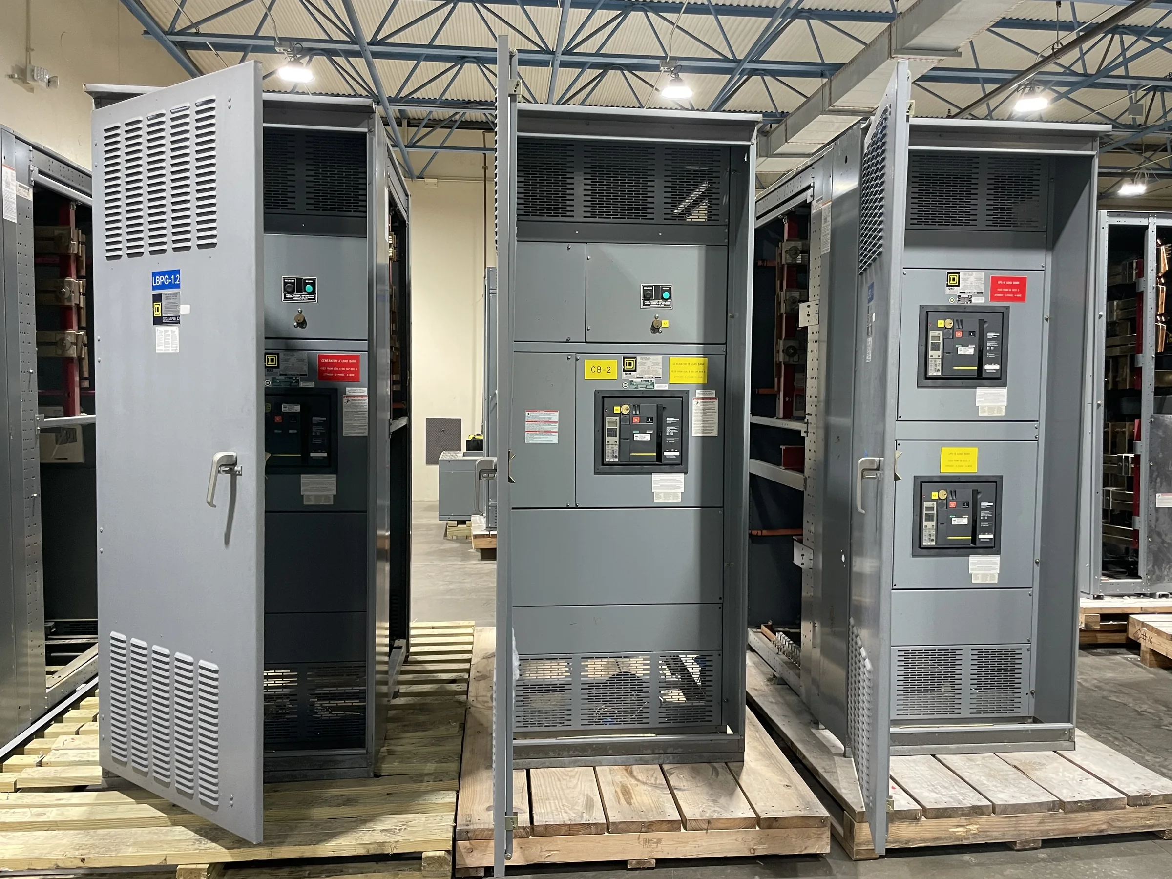
Define the Disconnect’s Role at the Service
A service entrance disconnect is more than a main breaker or switch selected by ampere rating. It sits at the point where utility conductors enter the customer’s distribution system, so the design must reflect the service arrangement, equipment function, and applicable installation requirements. Confirm whether the project calls for a service-rated switchboard, the number and arrangement of service disconnects, and whether downstream distribution is part of the same assembly. Utility requirements and the authority having jurisdiction can affect the acceptable configuration; resolve those questions before finalizing a purchase specification. Share the one-line diagram, service voltage and phase, available fault-current information, and project code basis for review. Clear scope prevents a disconnect assembly from arriving that cannot be accepted or integrated as intended.
Match Ratings and Protection to the System
The disconnect must suit the electrical system it serves, not simply match a requested current value. Specify nominal voltage, phase and wire arrangement, continuous current, and the available short-circuit current at the equipment location. The equipment short-circuit rating and protective-device characteristics need to be considered with the upstream utility source and downstream system; a rating cannot be assumed from the enclosure or breaker frame alone. Identify the required main device type and any ground-fault protection or other protective functions shown in the design. If a coordination or arc-flash study is underway, provide its relevant requirements and update the equipment schedule when conclusions change. Final ratings and protective features remain project-specific, so engineering review should precede approval and manufacture.


Document Conductors, Terminations, and Grounding
Conductor details influence both the termination space and the way the service equipment is built. Send the specified conductor material, quantity and size per phase, neutral requirements, and planned raceway entry locations; include any restrictions on top, bottom, or side entry. These details help identify whether cable bending room and lug arrangements can accommodate the installation without field changes. Service equipment also requires a defined grounding and bonding arrangement, including the neutral treatment and equipment grounding connections appropriate to the system. Avoid relying on assumptions drawn from an existing cabinet: the existing installation may differ from the new design or current project requirements. Provide drawings and utility interface information, then have the engineer, manufacturer, installer, and authority having jurisdiction resolve conflicts before release.
Check the Room, Access, and Installation Path
A correctly rated disconnect can still create a costly problem if it cannot be installed or safely accessed in its intended location. Verify available wall or floor space, working clearances, door swing, equipment orientation, and the path from the unloading point to the electrical room. Record doorway widths, corridor turns, overhead limits, floor loading concerns, and whether handling equipment can reach the final position. For replacement work, compare proposed dimensions and conduit entry points with the existing installation, but do not assume old foundations or raceways will align. Share site plans, photographs, and measured constraints during quotation and drawing review. Resolving these practical issues early can prevent rework, delivery delays, and last-minute changes to the room layout.
Coordinate Submittals, Approval, and Project Timing
Procurement timing depends on more than the date a purchase order is issued. A complete inquiry—with the one-line, equipment schedule, specifications, site constraints, and required documentation—gives the manufacturer a clearer basis to review the design and identify open decisions. Allow the project team time to evaluate drawings, confirm ratings and dimensions, and return consolidated comments before production release. State the required approval sequence, document format, project milestones, and any inspection or witness needs in the request. Custom builds and short lead times may be available, but actual scope, component availability, engineering review, and approval cycles affect timing. Ask for a project-specific schedule and confirm how design changes after approval could affect both manufacturing and the planned outage.
Plan Delivery and Verify the Final Equipment Scope
Delivery planning should account for the equipment’s dimensions, weight, packaging, unloading resources, receiving hours, and site access—not just the ship-to address. Nationwide shipping can support projects across the United States, but the customer and project team should coordinate carrier access, delivery appointments, staging, and any restrictions at the facility. Before ordering, define the submittal and closeout documents required, such as approved drawings, equipment identification, and applicable product documentation. UL 891 applies to appropriately evaluated low-voltage switchboard assemblies; it is not a blanket certification for medium- or high-voltage equipment, and a UL label should not be presumed for every configuration. Confirm the exact requested evaluation, ratings, components, and availability with the manufacturer and responsible project professionals.