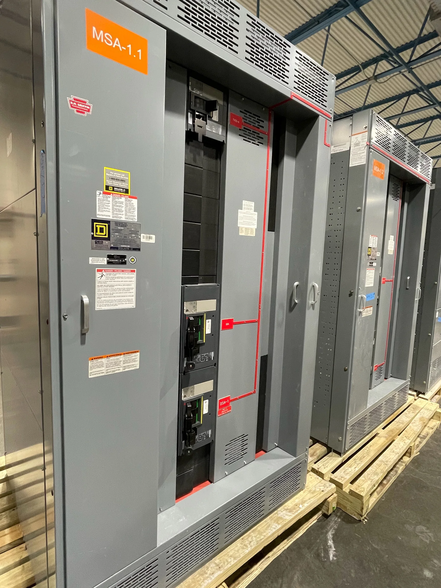
Define Access for the Work the Equipment Must Support
Serviceability begins with the tasks technicians are expected to perform over the equipment’s life: inspecting connections, operating devices, testing protective functions, replacing components, or adding circuits. Translate those tasks into enclosure access, working space, aisle layout, door swing, and removal paths before the lineup is fixed. A narrow electrical room may accommodate the equipment footprint yet leave no practical way to withdraw a breaker or move a replacement section. That can turn routine maintenance into a shutdown extension or require building alterations. During specification, identify which compartments need front access, whether rear access is available, and what clearances the applicable codes and equipment instructions require. Confirm those assumptions against the actual room plan, not a typical arrangement.
Coordinate Internal Layout With Maintainable Components
A compact arrangement can reduce floor-space demands, but packing devices tightly without considering inspection and replacement can create costly maintenance constraints. Ask the manufacturer to review how breakers, fuses, control components, and cable terminations are reached and removed in the proposed configuration. The answer depends on the selected equipment, ratings, construction, and intended service tasks; a familiar arrangement in one lineup should not be assumed to fit another. Review barriers, shutters, wiring ducts, and compartment divisions for how they affect access to the work area. If the project has preferred replacement components or an established maintenance approach, include that information with the request for quotation. Resolving layout questions before approval drawings are released is generally easier than revising a built assembly.


Design Cable Entry Around Real Field Conditions
Cable access decisions affect both equipment arrangement and installation effort. Identify incoming and outgoing conductor routes, whether entry is from above or below, the location of trenches or pull boxes, and the direction cables must turn to reach their terminals. Confirm the working room needed for bending, terminating, dressing, and inspecting conductors, using the project’s conductor and equipment requirements rather than assumed dimensions. Congested raceways or a misplaced structural beam can obstruct an otherwise suitable access route, while insufficient termination space can complicate commissioning and later maintenance. Provide the manufacturer with current electrical-room drawings and known site obstructions. Final cable provisions and clearances remain project-specific and should be reconciled with approved equipment drawings, applicable codes, and the installing contractor’s field conditions.
Plan Room Layout, Egress, and Safe Isolation
Service access is only useful when personnel can reach the equipment and carry out planned work under the site’s safety procedures. Show doors, adjacent walls, other electrical gear, columns, piping, ventilation equipment, and paths of travel on the room layout. Check that equipment doors can open without blocking an exit or colliding with neighboring equipment, and preserve required working space and access to disconnecting means. Maintenance planning should also identify how the relevant circuits will be isolated, verified de-energized, and returned to service by qualified personnel under site procedures. Do not assume an access panel or a convenient operating handle makes energized maintenance appropriate. Have the project engineer and safety team review the arrangement against applicable requirements before equipment release.
Use Drawings and Submittals to Resolve Access Questions
A useful submittal review checks more than overall dimensions. Compare the proposed front, rear, and side access conditions with the room plan; confirm device orientation, cable entry, door swing, lifting provisions, and the route for moving sections into the building. Review elevation and floor-plan drawings alongside one-line diagrams, equipment schedules, control requirements, and installation constraints so conflicting assumptions surface early. Mark required maintenance tasks or preferred component access directly in the review comments rather than relying on informal conversations. Clarify which drawings are preliminary and which are approved for fabrication, and route changes through the project’s documented review process. Accurate, coordinated documents help limit field modifications, but the installing team must still verify actual site dimensions before delivery and placement.
Align Manufacturing and Delivery With the Installation Window
The schedule for new switchgear should reflect the time needed to finalize project-specific details, review drawings, manufacture the assembly, prepare the site, and coordinate delivery and setting. Short lead times may be available, but timing depends on the approved scope, component availability, design decisions, and current production conditions; obtain project-specific confirmation rather than relying on a generic promise. Check whether the equipment can travel from the receiving point to its final location through doors, corridors, loading areas, elevators, or a crane pick. Confirm shipping configuration, unloading responsibility, storage conditions, and whether the room will be ready when the assembly arrives. A U.S. manufacturer can discuss nationwide shipment, but the customer and project team should coordinate route, access, and installation dates before committing to a turnover plan.