Define the Electrical Boundary Before Selecting Equipment
Solar and storage projects can connect at a facility’s main service, a dedicated distribution lineup, or another point established by the approved system design. Identify that boundary before requesting switchgear pricing: it determines which sources, loads, and protective devices the equipment must accommodate. Provide one-line diagrams showing utility service, photovoltaic inverters, battery power conversion equipment, generators, and major loads, including proposed operating modes. A system that exports power, supports an islanded microgrid, or provides backup may require different switching and protection arrangements than a non-exporting installation. The manufacturer can use project documents to develop a new equipment proposal, but the engineer of record and utility determine applicable design requirements and connection approval. Confirm the final division of responsibility before equipment drawings are released.
Coordinate Ratings, Fault Duty, and Protection
The equipment’s voltage class, continuous current, short-circuit rating, bus arrangement, and protective-device details must suit the actual system and available fault-current study; they are not interchangeable placeholders. Solar inverters and battery converters contribute fault current differently from conventional rotating generators, so protection settings and selective coordination should reflect the specific equipment and operating scenarios. Ask the inverter and storage suppliers for current-limiting behavior, fault contribution, and disconnect information, then have the project engineer assess those inputs against utility data and existing distribution equipment. A proposed switchboard or switchgear lineup must also be checked for compatibility with the upstream service and downstream loads. Document assumptions in the request for quotation so changes in utility fault duty or system architecture are caught before approved drawings and procurement are locked.


Plan Interconnection, Isolation, and Operating Modes
A battery system may charge from solar, the utility, or both, and it may discharge to facility loads or the grid. Those operating choices affect interconnection equipment, metering, isolation points, and controls. Identify whether the project is grid-following, designed for intentional islanding, or limited to backup operation; do not assume a lineup intended for one mode will support another. The utility’s interconnection requirements, the engineer’s protection scheme, and the controls contractor’s sequence of operations should agree on how sources connect and disconnect. Show normal, maintenance, fault, and transition conditions on drawings or a written operating narrative. This coordination helps define the required device functions and avoids late redesign when an approved control sequence conflicts with the equipment layout or utility review.
Check the Site, Access Route, and Installation Sequence
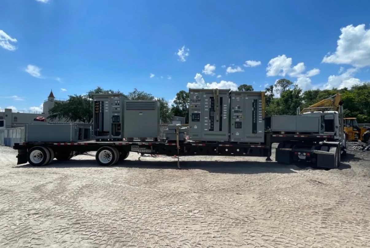
A technically suitable lineup can still create a field problem if the electrical room, access path, or installation sequence cannot accommodate it. Confirm available floor area, clearances, ceiling height, door and corridor dimensions, floor loading, cable-entry direction, and the route from the unloading point to the final position. Solar and storage projects often add equipment around an operating facility, so identify shutdown windows, temporary power needs, and any requirement to stage installation in sections. Provide site plans, room elevations, and known lifting or access restrictions with the bid package. The manufacturer can review proposed equipment configuration against supplied constraints, but the project team must verify field conditions and code-required working space. Resolve these details before approving drawings to reduce delivery, rigging, and installation conflicts.
Build a Complete Procurement and Drawing Package
A focused request for quotation gives the manufacturer enough information to identify gaps without treating unconfirmed assumptions as commitments. Include the one-line diagram, load and source data, system voltage, requested ratings, protection requirements, utility criteria, indoor or outdoor location, environmental conditions, and preferred cable or bus connections. Add the project schedule, drawing-submittal milestones, approval contacts, and required shipping destination. For a low-voltage switchboard, UL 891 may be relevant when the proposed assembly is appropriately evaluated for that standard; it does not establish a blanket listing for medium- or high-voltage equipment. State required standards or labeling explicitly and confirm applicability for the actual assembly. Review the manufacturer’s drawings for interface dimensions, device functions, and connection details before release for production.
Coordinate Schedule, Delivery, and Commissioning Interfaces
Procurement timing depends on the approved scope, component availability, drawing review, and project-specific build requirements; a short lead time should be discussed, not presumed. Ask early for the current schedule basis and identify dates when utility approval, inverter selection, battery-system data, and site readiness will be available. Confirm the shipping destination, receiving hours, unloading equipment, storage conditions, and whether phased delivery is needed to match construction. Nationwide shipping does not remove the project team’s responsibility to prepare a safe route and suitable receiving area. Before turnover, coordinate equipment documentation with the installing contractor, protection engineer, controls provider, and commissioning team. Final settings, testing, energization, and acceptance belong to qualified project personnel under approved procedures; ensure de-energized work and required safety controls are planned.