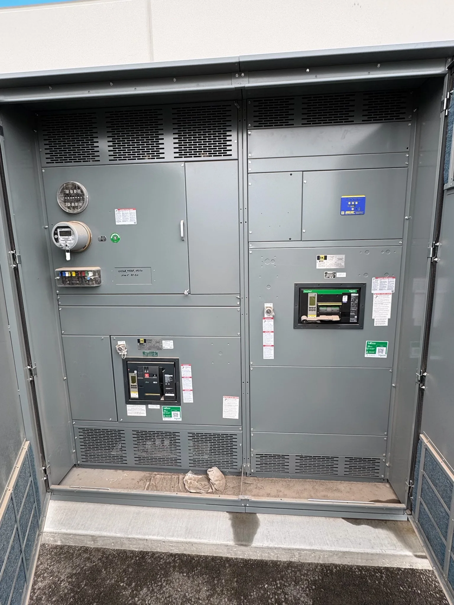
Start With the Exposure and the Equipment Boundary
Surge protection planning begins by identifying what can introduce a transient and which parts of the distribution system must remain protected. Utility switching, nearby lightning activity, large motors, and other site loads can affect the exposure, but the right arrangement depends on the service, grounding and bonding design, and equipment configuration. Map the path from the service entrance through switchboards, distribution panels, and sensitive loads; protection at one point does not automatically protect every downstream circuit. For a new assembly, give the manufacturer the one-line diagram, available fault-current information, system voltage and grounding method, and the location of critical loads. Those inputs let the project team evaluate where protection belongs and what coordination questions require review by the engineer of record.
Specify Protection Without Treating It as a Standalone Add-On
A surge protective device (SPD) must suit the electrical system and the assembly where it will be installed. The specification should identify the intended connection point, nominal system characteristics, grounding arrangement, and applicable performance and installation requirements, while leaving final selection subject to design review. Confirm whether the project calls for an SPD integral to a switchboard or a separately installed device; the choice affects space, wiring, service access, and coordination with upstream overcurrent protection. Ask how the proposed configuration will be represented in the shop drawings and equipment documentation, and whether the device can be inspected or replaced without disturbing unrelated equipment. Do not assume an existing device schedule transfers unchanged to new gear: verify compatibility against the actual one-line and project requirements.


Coordinate Protection With Overcurrent and Grounding Design
Surge protection does not replace short-circuit protection, grounding, bonding, or sound system design. The engineer should review the SPD’s connection and protective-device requirements alongside available fault current, upstream devices, and the assembly’s intended ratings. A mismatch can create a design conflict, complicate review, or leave installation details unresolved until the equipment is on site. Provide the manufacturer with the current one-line, protective-device schedule, grounding details, and any owner or consultant requirements early enough for questions to be addressed before drawing approval. Confirm who owns calculations and final coordination decisions; equipment suppliers need project inputs but should not be treated as a substitute for the engineer of record. Document accepted revisions so the issued drawings, approved submittals, and field installation describe the same design.
Resolve Physical Layout and Maintenance Access Early
The physical arrangement matters as much as the device selection. An SPD may require a suitable mounting location, connection routing, and access for status checks or replacement; actual space and wiring arrangements depend on the equipment design and project requirements. Review the proposed section layout against room clearances, cable-entry direction, bus and termination locations, ventilation, and the facility’s maintenance practices. In retrofit work, capture existing conditions, including conduit positions, available wall or floor space, and restrictions on shutdown windows. For new construction, coordinate the switchboard footprint and cable approach with structural, architectural, and electrical drawings before they are frozen. These checks reduce the risk of field changes, obstructed access, or a protection device that is technically specified but awkward to inspect and maintain.
Build Submittal and Schedule Decisions Around Real Inputs
Surge-protection decisions can affect equipment drawings, component selection, and procurement coordination, so raise them before the switchgear design is released for fabrication. A complete request for quotation should identify the project voltage and grounding, service arrangement, one-line diagram, required protection locations, applicable specifications, and target ship-to date. Include the owner’s preferred device requirements when established, but flag open engineering decisions rather than guessing at them. Review submittals for the device location, connection notes, equipment ratings, and alignment with the approved design; resolve exceptions in writing. A U.S. manufacturer can discuss custom-built equipment, American components, short lead-time options, and nationwide shipping, but timing and availability are project-specific. Confirm the current schedule, approval milestones, and delivery assumptions directly for the configuration being quoted.
Plan Delivery, Installation, and Handover Together
A protection plan is incomplete until the equipment can reach the electrical room, be installed, and be maintained safely. Before shipment, verify the delivery address, receiving hours, unloading responsibility, access route, door and corridor dimensions, floor capacity, and any staging limits. Coordinate shipping sequence with site readiness and the installation plan; a delivered assembly can be difficult to protect or position if the room is unfinished or access is blocked. During commissioning, qualified personnel should verify installation against approved drawings and manufacturer instructions, with equipment de-energized wherever work requires it and established site safety procedures followed. Collect final drawings, device documentation, and maintenance information for the facility record. These records help future teams identify the installed configuration, check device condition, and evaluate changes without relying on assumptions.