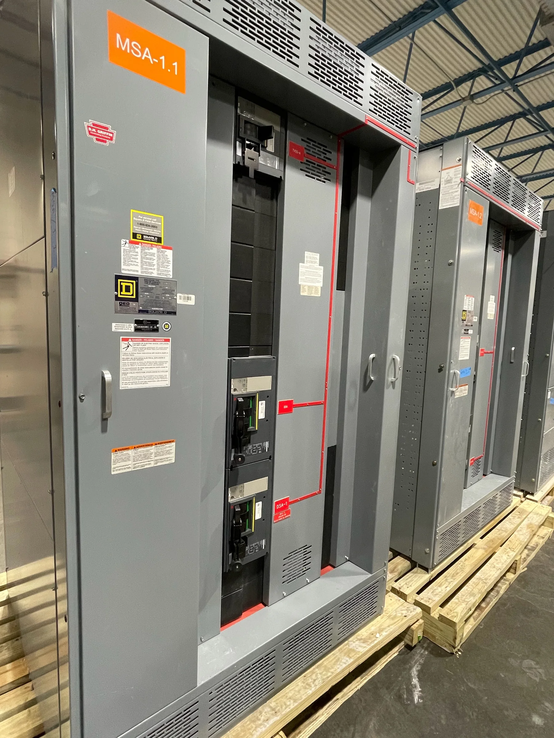
Define What Temporary Power Must Support
Temporary power planning starts with the loads and work phases the system must serve, not with a switchgear catalog. Identify construction tools, temporary lighting, pumps, heaters, process equipment, trailers, and any loads that must remain available during a transition. For each, document voltage, phase, estimated demand, starting characteristics, duty cycle, and whether it can operate at the same time as other loads. This matters because motor starting or coincident demand can affect equipment selection even when the average load appears modest. Ask the project engineer to distinguish confirmed loads from allowances and future expansion. The resulting load schedule gives the manufacturer and electrical contractor a shared basis for discussing a new assembly, feeder arrangement, source connection, and practical operating sequence.
Set the Source, Distribution, and Protection Boundaries
Clarify where temporary power begins and ends: utility service, generator terminals, an existing distribution point, the new switchgear, and downstream panels or equipment. Record available source information, grounding arrangement, system voltage, fault-current data, and the protective devices already in the path; do not assume a generator and utility source present the same conditions. These details influence coordination, equipment ratings, and whether a proposed arrangement is compatible with the installation. A qualified engineer should establish the protective-device strategy and review any transfer or parallel-source concept. For procurement, provide one-line diagrams, source data, and known interface constraints early. Missing fault-current or grounding information can force design clarification and affect the suitability of equipment, so resolve uncertainties rather than treating preliminary values as final.


Choose an Arrangement That Fits the Work Sequence
Temporary distribution may be needed for one construction phase, a planned outage, equipment replacement, commissioning, or a longer transition to permanent service. Map the sequence: what must be energized first, which loads move later, and whether any areas need separate control or isolation. A temporary arrangement sized only for the first phase may become inadequate when construction loads overlap with startup or commissioning loads. Conversely, carrying every possible future load in the initial scope can add cost and complexity without a defined need. Ask the design team to identify phases, expected load changes, and any required changeover points. Discuss those assumptions with the manufacturer before finalizing the new equipment configuration; changes to feeder positions, control interfaces, or enclosure layout are harder to address after drawings are approved.
Coordinate Specifications, Reviews, and Procurement
A useful request for quotation package combines the load schedule with the one-line diagram, equipment location, service conditions, cable entry preferences, and required interfaces. Include the project’s governing specifications and identify which requirements are mandatory, preferred, or still under review. If a low-voltage switchboard assembly is expected to meet UL 891, state that requirement for the applicable assembly and confirm the proposed scope and evaluation with the manufacturer; it is not a blanket designation for medium- or high-voltage equipment. Review submittals for ratings, dimensions, access, connection details, and alignment with the latest drawings. Clear review responsibility and response dates help avoid procurement holds. Exact configuration, standards applicability, listing, and availability depend on the project and should be confirmed before release for manufacture.
Plan the Site, Connection, and Safe Changeover
The electrical room, temporary pad, or staging area can constrain the design as much as the load. Confirm footprint, working and access clearances, door and corridor dimensions, floor or pad capacity, environmental exposure, ventilation, and the route for incoming and outgoing conductors. Check cable lengths and bending space against actual entry locations; a connection that works on a drawing may be impractical behind a wall or beside adjacent equipment. Establish who provides supports, grounding connections, barriers, and weather protection. Most importantly, document how the installation will be isolated, verified de-energized, and placed into service by qualified personnel under the project’s safety procedures. A changeover plan should identify outage windows, responsible parties, testing and inspection steps, and contingencies without relying on energized installation work.
Align Delivery With Receiving and Project Milestones
Nationwide shipment does not remove the need for a site-specific receiving plan. Compare the requested ship window with room readiness, foundation completion, access availability, crane or material-handling arrangements, and the date the electrical contractor can safely install the assembly. Ask the manufacturer which shipment dimensions and handling details are available for the quoted configuration, then verify that the route from unloading point to final location can accommodate them. Assign responsibility for unloading, inspection, storage, protection from weather, and reporting transit damage. Confirm delivery coordination and current availability in writing; custom equipment timing depends on approved documentation, materials, production conditions, and project changes. A realistic schedule includes time for drawing review, approval, shipment, installation, inspection, and commissioning—not just the date equipment is expected to leave the factory.