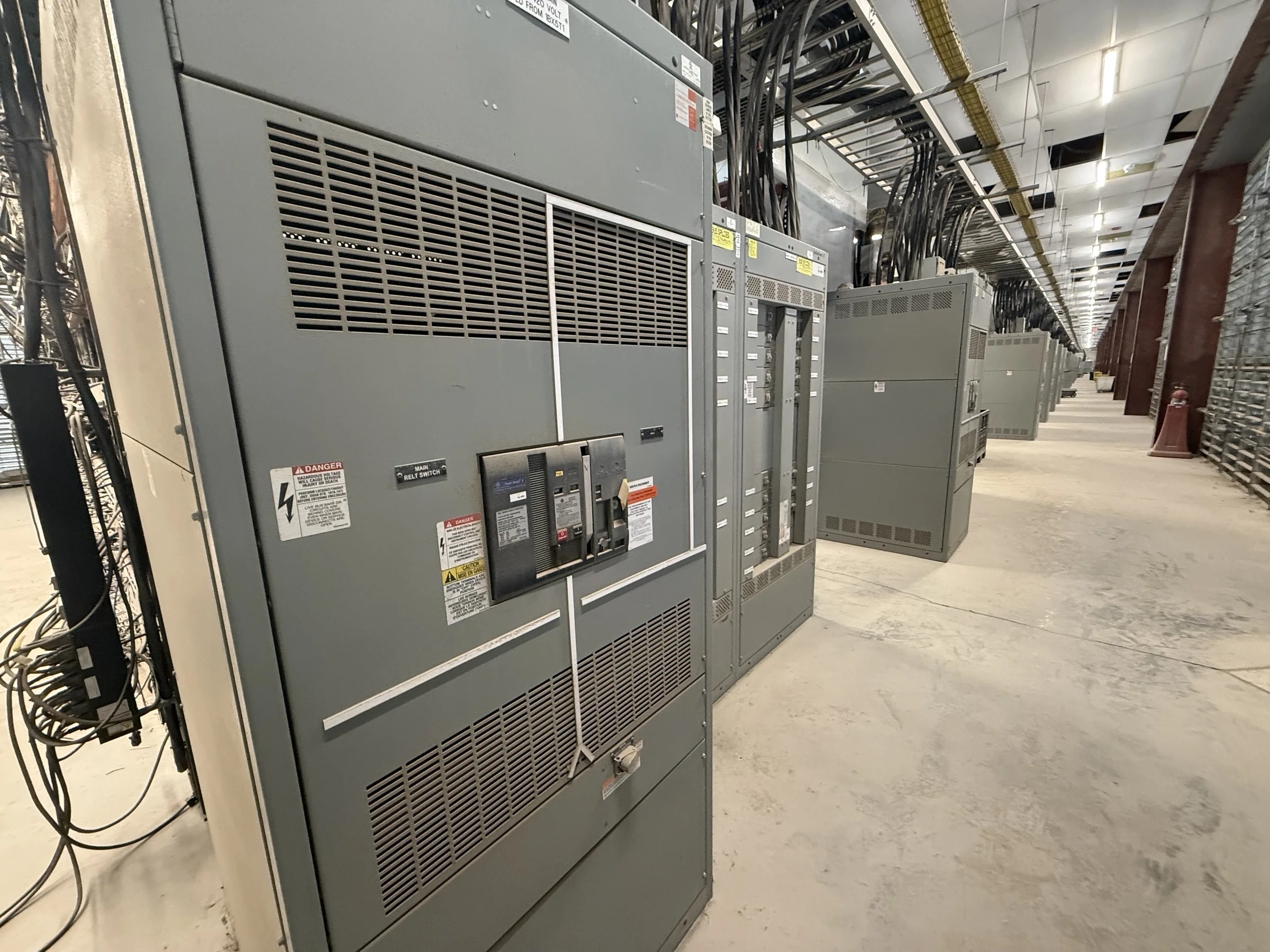
Define What the Voltage Transformer Must Do
A switchgear voltage transformer (VT), also called a potential transformer in some specifications, scales system voltage to a level suitable for metering, protective relays, or control circuits. Begin by identifying the connected functions and the phase-to-phase and phase-to-ground voltages they must measure. The grounding method and system configuration matter: a transformer arrangement intended for one system may not provide the required measurements or ground-fault indication on another. Specify whether the VT is for indoor or outdoor service, its intended mounting location, and whether it will be installed in a new lineup or as part of a replacement project. These details shape the design review and help prevent a physically compatible transformer from being electrically unsuitable.
Match Accuracy, Burden, and Protection Needs
Connected devices impose a burden on each VT secondary, and the required accuracy depends on how the signal will be used. Metering and protective relaying may call for different accuracy classes or secondary arrangements; simply matching nominal voltage is not enough. List the instruments, relays, control devices, and expected simultaneous loads, then have the design team verify the transformer’s burden and intended performance against the applicable project requirements. Also clarify whether separate secondary windings or circuits are needed for distinct functions. Fusing and isolation provisions should be coordinated with the switchgear design and the protection scheme, rather than selected in isolation. A clear application schedule reduces the risk of inaccurate readings, nuisance operation, or late revisions after the lineup layout is established.


Coordinate the VT With the Switchgear Lineup
Voltage transformers affect compartment layout, access, wiring routes, and the overall assembly, so include them in the switchgear specification early. Confirm the intended compartment and connection arrangement, the primary and secondary termination approach, and how the VT will be isolated for inspection or replacement. Where a project calls for drawout equipment, verify that the specified construction and interlocking requirements match the lineup design; do not assume every VT assembly is interchangeable. For retrofit work, provide existing switchgear manufacturer and model information, available drawings, photographs, and measured compartment details when available. Differences in bus arrangement, clearances, and control wiring can prevent a nominally similar transformer from fitting or integrating correctly. A documented compatibility review helps limit field modifications and schedule disruption.
Specify Interfaces, Ratings, and Documentation
A useful procurement package identifies system voltage, frequency, grounding, insulation requirements, intended service, VT ratio, secondary voltage, accuracy needs, burden, and connection diagram. Include project standards, environmental conditions, and any required control or protective functions, but distinguish mandatory requirements from preferences. Request drawings that show the proposed arrangement and relevant primary and secondary connections so engineering and operations teams can review interfaces before release. For a new lineup, coordinate the VT requirements with the switchgear one-line diagram, elementary diagrams, equipment schedules, and protection documentation. If a low-voltage switchboard is involved, any UL 891 evaluation applies to appropriately evaluated assemblies, not automatically to each transformer or to medium-voltage equipment. Final ratings, standards, and labeling remain subject to the project design and equipment evaluation.
Plan Review, Build Timing, and Delivery
VT selection can influence enclosure details and wiring, so settle the application before approving production drawings. Ask the manufacturer to identify the submittal information needed for engineering review and to confirm project-specific availability and timing; do not base a construction schedule on an assumed standard configuration. Allow time for owner, engineer, and contractor comments, drawing revisions, and coordination with the complete switchgear release. Delivery planning should account for the destination’s receiving hours, unloading equipment, staging space, access restrictions, and whether the lineup will arrive in sections. A site with limited laydown area may require closer coordination of shipment sequencing and installation readiness. Nationwide shipping does not remove the need to verify route, carrier access, site handling responsibilities, and delivery conditions before shipment.
Prepare for Installation and Future Maintenance
Before installation, compare the approved drawings and equipment nameplates with the project documents, and resolve discrepancies through the responsible engineering and manufacturer contacts. The installation plan should address lifting, placement, secondary wiring, grounding, protection coordination, and required inspections under the project’s approved procedures. Electrical work must be performed by qualified personnel with equipment de-energized and secured under applicable safety practices; testing or commissioning should follow the approved plan and equipment instructions. For ongoing maintenance, retain transformer data, connection diagrams, settings or relay records, and inspection history with the switchgear documentation. Clearly identifying which VT serves each metering or protection function makes troubleshooting more efficient and reduces the chance of disturbing the wrong circuit. Confirm replacement compatibility from actual equipment details rather than relying on appearance alone.