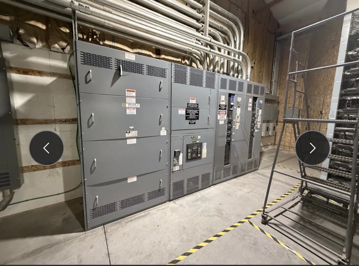
Measure the Working Space Before Equipment Is Specified
Working clearance is the usable space needed to operate, inspect, and maintain electrical equipment—not simply the distance from a cabinet to the nearest wall. Before requesting a quote, document room dimensions, equipment locations, door swings, columns, floor openings, and fixed obstructions such as piping or ductwork. Identify the equipment voltage and the conditions on each side of the installation, since applicable clearance requirements depend on the equipment and its arrangement. A measured floor plan helps the design team assess whether the proposed lineup can be installed and serviced without blocking an aisle or access route. Include dimensions from finished surfaces, and distinguish permanent obstructions from items expected to move. Early, accurate measurements can prevent costly layout revisions after the switchgear has been specified or delivered.
Confirm Applicable Electrical and Building Requirements
Required working space is determined by applicable electrical codes, the equipment’s characteristics, and the site conditions; a single clearance figure should not be assumed for every installation. Have the responsible electrical engineer or qualified design professional identify the governing requirements and document the basis for the layout. Confirm whether the space in front of the equipment must remain dedicated, what access is needed at the rear or sides, and whether doors or removable covers affect the available space. Also coordinate with the authority having jurisdiction and facility standards where applicable. These decisions matter because a lineup that physically fits may still be difficult to operate, maintain, or approve. Provide the manufacturer with the approved arrangement and project requirements so equipment configuration can be evaluated against the actual installation.


Coordinate Doors, Aisles, and Routine Maintenance
A clearance plan should account for equipment in use, not just the footprint shown on a drawing. Check that personnel can approach operating handles, read instruments, and open doors without colliding with nearby equipment or obstructing an egress route. Consider how technicians will access inspection points and remove components during maintenance, following the equipment documentation and site safety procedures. Where two lineups face one another, evaluate how their doors and working areas interact; a clear aisle on paper can become restricted when both sides are open. Mark equipment faces and door swings on the floor plan, then review the arrangement with operations and maintenance staff. Their input can reveal routine tasks or traffic patterns that an architectural plan alone may not show.
Include the Full Installation and Room Environment
Clearance planning also depends on conditions that affect installation and long-term access. Record ceiling height, floor loading information available to the project team, housekeeping pads, trenches, cable entry locations, and the route from the receiving point to the equipment room. Note heat sources, moisture concerns, dust, corrosive exposure, and ventilation constraints; these conditions can influence equipment selection or room planning and should be reviewed with the engineer and manufacturer. Identify sprinkler piping, lighting, fire-rated walls, and other overhead or adjacent services that could limit access or future maintenance. This information matters because a switchgear lineup may fit its designated footprint while still being impossible to move into position or service safely. Treat the equipment-room plan and the delivery path as connected design constraints.
Send a Complete Clearance Package With the Quote Request
A useful request for quotation includes more than a desired lineup length. Send the latest floor plan, equipment schedule, one-line diagram, available room elevations, cable-entry preferences, and any project-specific clearance criteria. Identify whether drawings are preliminary or approved, and list open questions rather than presenting uncertain dimensions as fixed. Clarify the intended equipment application and required electrical characteristics so the proposed configuration can be reviewed in context. For low-voltage switchboard assemblies, UL 891 may be relevant when applicable to the project and the particular assembly; it is not a blanket certification for all switchgear or voltage classes. Complete documentation helps the U.S. manufacturer identify configuration questions early, while leaving final suitability, standards, ratings, and evaluation subject to project-specific review.
Align Approval Drawings, Schedule, and Delivery Access
Working clearance decisions should remain visible through drawing review, procurement, and site delivery. Assign a reviewer to check equipment dimensions and required access against the current architectural and electrical plans, and reconcile revisions before approving production drawings. Confirm who will verify field measurements, prepare the equipment room, and coordinate receiving, unloading, and movement to the final location. Nationwide shipping and short lead times may be available offerings, but project timing and delivery arrangements depend on the specific order, equipment, and site. Share access restrictions, receiving hours, lift or rigging constraints, and any staging limits early so they can be considered during planning. A coordinated schedule matters: equipment arriving before the room and route are ready can create storage, handling, and installation problems that a clearance review could have prevented.