Choose the Entry Direction Around the Feeder Route
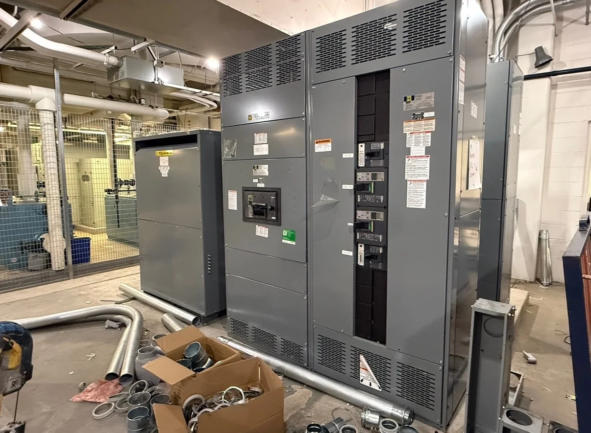
Top entry and bottom entry describe where conductors approach and enter a switchgear lineup; neither is automatically the better arrangement. Start with the actual feeder path from the source, transformer, cable tray, bus duct, or underground duct bank, then compare it with the proposed equipment location. A top approach may align with overhead tray or busway, while a bottom approach may suit an underground raceway route. The distinction matters because a convenient cable path can reduce bends and congestion, but it must also preserve required clearances and access. Share a one-line diagram and a preliminary room layout with the manufacturer early. The final entry arrangement depends on conductor type, equipment design, ratings, and project-specific evaluation—not on the entry direction alone.
Check Room Geometry, Working Space, and Cable Access
Before selecting an arrangement, map the room in plan and elevation, including doors, columns, overhead obstructions, floor openings, and nearby equipment. Top-entry conductors need a feasible route above the lineup and enough room to make connections without obstructing access or violating applicable clearances. Bottom-entry conductors require coordinated trenches, sleeves, or floor penetrations, and their locations must land where the equipment can accept them. A mismatch can force field rerouting, interfere with maintenance, or delay installation while concrete or building work is revised. Provide measured dimensions and identify fixed obstacles rather than relying on a schematic footprint. Confirm working space, cable bend requirements, access provisions, and equipment-specific connection limits with the responsible engineer and manufacturer.


Coordinate Conductors, Terminations, and Entry Sections
The entry choice affects more than the point where a cable crosses the enclosure boundary. Engineers must coordinate conductor material and size, quantity, insulation, lug arrangement, bending space, termination orientation, and whether the design uses cable or bus connections. Large conductors may need more space to turn and reach their terminals; several parallel sets can make an apparently simple route crowded. With top entry, consider how supports and overhead routing affect pulling and termination. With bottom entry, verify that raceway positions and the equipment's incoming section align. Do not assume a standard compartment can accommodate every configuration. Include preliminary cable schedules and connection details in the RFQ, then confirm final dimensions and compatibility against approved submittals before releasing construction.
Resolve Building Interfaces Before Equipment Is Released
Entry openings connect electrical design to structural, architectural, and civil work. For bottom entry, floor sleeves, housekeeping pads, trenches, and duct-bank stub-ups must be positioned in relation to the finalized lineup and its connection points. For top entry, supports, tray elevations, roof or ceiling penetrations, and any water-management details may affect the route. If these interfaces are coordinated late, crews can discover that embedded conduits miss the intended section or that overhead services conflict with access. Identify who owns each opening, support, seal, and firestop in the project documents. Use current equipment drawings—not preliminary assumptions—for field layout. Changes to openings or entry locations should be reviewed for equipment suitability, building-code obligations, and the project’s installation sequence.
Put Entry Requirements Into the RFQ and Submittal Review
A useful request for quotation states the intended entry direction, source location, feeder arrangement, available room dimensions, and known constraints, while identifying items that remain subject to engineering. Attach the one-line diagram, site plan, cable schedule, and relevant specifications, and note whether the project anticipates future feeders or spare capacity. Ask the manufacturer to identify the proposed incoming section and show connection space, access, and interface dimensions in the submittal. Review those drawings with the electrical engineer, installer, and other trades before approval; a general note such as “top feed” cannot resolve every routing detail. The manufacturer can develop new equipment around project requirements, but exact design, ratings, standards, and compatibility must be confirmed for the specific assembly.
Plan Manufacturing, Delivery, and Installation as One Sequence
Entry direction can influence site readiness and the order in which equipment and conductors arrive. Bottom-entry work may depend on completed duct banks, floor penetrations, and verified stub-up locations; top-entry work may require tray, busway, or overhead supports to be coordinated with the lineup. Discuss these dependencies, drawing approvals, shipping configuration, unloading access, and receiving conditions with the U.S. manufacturer when requesting a quote. Custom builds, American components, short lead times, and nationwide shipping are offerings to discuss, not guaranteed schedules or a substitute for project-specific confirmation. Establish delivery milestones only after scope, approvals, and availability are reviewed. Before installation or termination, follow the approved procedures and ensure equipment is de-energized for the work.