Define What 277/480V Distribution Must Serve
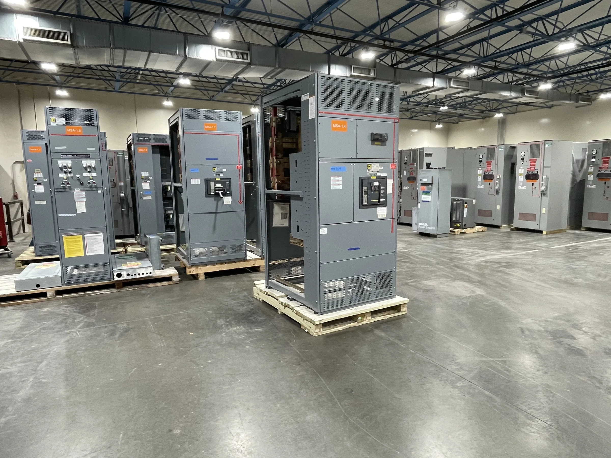
A 277/480V system commonly supports three-phase distribution, including 480V equipment loads and 277V lighting, but the actual lineup should follow the facility’s electrical design—not a voltage label alone. Start with the one-line diagram, service and source information, connected and future loads, and the intended distribution arrangement. Engineers should confirm system grounding, available fault current, required interrupting ratings, and coordination with upstream and downstream protective devices. These details affect bus and breaker selections and whether a proposed assembly fits the existing electrical system. Identify whether the project calls for a switchboard or another type of switchgear; terminology and applicable product standards depend on the equipment design. Final ratings, construction, and standards are project-specific and should be reviewed against the approved design.
Choose an Assembly Around Loads and Operating Needs
Load mix influences how a 277/480V lineup is arranged. Motors, HVAC equipment, pumps, process machinery, and lighting may call for different feeder sizes, protective-device characteristics, metering, or control provisions. Document each major load and its expected operating profile, then account for starting current, demand, planned expansion, and any critical loads that require a defined operating sequence. If operators need to isolate sections or maintain service during planned work, that requirement should be resolved during design rather than assumed from the word “switchgear.” Space for cable entry, bending, termination, and future circuits also affects section layout. Share equipment schedules and control-interface requirements with the manufacturer so the proposed build can be checked against the engineer’s design and the facility’s intended use.


Coordinate Fault Ratings, Protection, and Applicable Standards
The assembly’s suitability depends on more than nominal voltage. Available fault current at the equipment, protective-device ratings, bus configuration, and the electrical system’s grounding method all need to align with the project documents and applicable requirements. Have the engineer establish the fault-current basis and protection study assumptions; do not substitute a rating simply because it appears familiar from another site. For low-voltage switchboard assemblies, UL 891 may be relevant when the equipment is appropriately evaluated to that standard. It is not a blanket certification for all switchgear or for medium- and high-voltage equipment. Request documentation describing the specific assembly, ratings, and evaluation applicable to the proposed product, and confirm acceptance requirements with the project’s authority having jurisdiction.
Resolve the Existing-Site Fit Before Replacing Equipment
Replacement work often turns on dimensions and interfaces that are absent from a voltage designation. Record the existing lineup footprint, room access, cable and bus connections, conductor sizes, phase arrangement, grounding provisions, and incoming-source details. Check door swing, working space, overhead obstructions, housekeeping pads, and the route from the unloading point to the electrical room. A new assembly may require changes to conduits, feeders, supports, or protection coordination even when its voltage matches the equipment being replaced. Provide available drawings, field measurements, nameplate information, and photographs for engineering review, while treating field verification as essential where records are incomplete. Identify outage and cutover constraints early so the replacement scope can be coordinated with the facility’s safety procedures and approved work plan.
Plan Submittals, Build Timing, and Delivery Together
Custom construction and short lead times can support project schedules, but timing depends on the approved scope, component availability, drawing review, and production requirements. Ask for a project-specific schedule after supplying the required electrical and mechanical information; do not base an outage or construction milestone on an unconfirmed delivery estimate. Establish who reviews and approves shop drawings, which documents are required, and how revisions will be handled. Nationwide shipping is an available offering, yet delivery planning still depends on destination access, unloading equipment, receiving hours, shipment dimensions, and site storage. Coordinate the carrier’s arrival with the general contractor or facility team, particularly where a narrow gate, restricted dock, crane pick, or active operating area could delay placement. Keep procurement, engineering, and site logistics aligned.
Prepare Documentation for Installation and Turnover
A complete equipment package helps installers and facility staff work from consistent information. Procurement documents should identify the required voltage, system arrangement, lineup configuration, feeder and protective-device schedule, metering or control needs, and applicable project standards. Review the submittal against the one-line diagram and equipment schedules before release, resolving discrepancies in ratings, connection points, dimensions, and accessories. For installation planning, confirm the approved drawings, equipment handling instructions, grounding and bonding details, and manufacturer-provided documentation are available to the responsible contractor. Energization and acceptance activities must follow the project’s approved procedures and applicable requirements; de-energized work is not optional. At turnover, retain the final drawings and equipment records, and make sure operations staff understand the installed configuration and maintenance information supplied for that assembly.