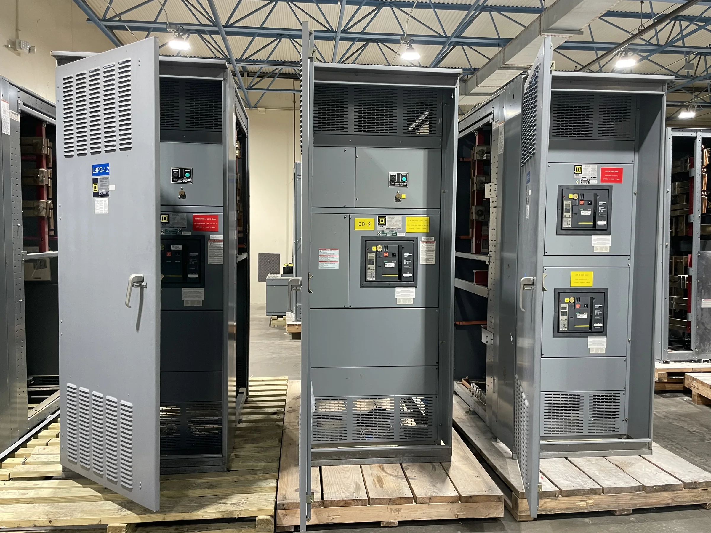
Define the 600 V Distribution Scope
A 600 V designation identifies a voltage class, not a complete equipment specification. Start by documenting the system voltage, phase and frequency, grounding arrangement, available fault current, and the loads the assembly must serve. Clarify whether the project calls for a low-voltage switchboard, switchgear, or coordinated distribution equipment; those terms do not automatically describe interchangeable assemblies or functions. Include main and feeder requirements, metering, protective devices, and any planned connection to generators, transformers, or downstream panels. These details help the manufacturer assess the proposed configuration rather than quote against a voltage label alone. Confirm applicable codes, project standards, and any required evaluation or labeling for the specific assembly. UL 891 applies to appropriately evaluated low-voltage switchboard assemblies, not every product described as 600 V equipment.
Coordinate Ratings and Protection Requirements
Protection choices depend on the installation’s electrical study and operating needs. Provide the latest available short-circuit and coordination information, including the source transformer data, utility contribution, and relevant upstream protective-device details. The engineer of record should establish required interrupting or withstand ratings and confirm that the proposed lineup fits the calculated available fault current. Ask how the specified breakers, fuses, or other devices affect selective coordination, maintenance, and replacement planning; do not assume a device family or rating is suitable solely because it fits a 600 V system. Where arc-flash or coordination studies are required, keep equipment decisions aligned with their documented assumptions and review process. Final ratings, protective-device combinations, and compliance obligations require project-specific confirmation before release for manufacture.


Match the Lineup to Loads and Operations
A distribution assembly has to support how the facility operates, not just its connected load total. Prepare a current and planned load schedule that identifies continuous, intermittent, motor, and other significant loads, plus expected expansion or spare feeder needs. Note which circuits are essential, whether transfer or alternate-source arrangements are part of the project, and how shutdowns can be scheduled for future service. These distinctions influence section arrangement, feeder provisions, metering, and coordination with adjacent equipment. Identify environmental conditions such as indoor or outdoor placement, ambient temperature, dust, moisture, corrosive exposure, and available ventilation. Site conditions can affect enclosure and installation decisions, so describe them early instead of relying on a generic 600 V configuration. Have the responsible engineer verify the final design.
Resolve Space, Access, and Connection Constraints
Before approving a layout, compare the proposed footprint and access clearances with verified field dimensions. Record doorway and corridor widths, ceiling height, floor loading concerns, working space, cable entry direction, and the route from unloading point to final position. Existing facilities may impose tight turns, overhead obstructions, or limited outage windows; each can change how sections are arranged, shipped, staged, or moved into place. Document conduit locations, busway interfaces, cable sizes and termination requirements when known, and identify which connections are existing versus new. Confirm equipment access for operation and maintenance as well as the space needed to install it. Drawings should be reviewed against actual site conditions by the project team; a quotation or preliminary layout is not a substitute for field verification.
Prepare a Complete, Reviewable Submittal
A useful request for quotation gives the manufacturer enough information to identify open decisions. Include one-line diagrams, load schedules, preliminary layouts, equipment schedules, specifications, short-circuit and coordination requirements, and any preferred components or approved-equal rules. State required metering, controls, communications interfaces, enclosure conditions, and spare provisions, distinguishing mandatory items from preferences. Ask which drawings and technical documents will be available for review, and establish who must approve them before production release. Compare proposals by configuration, stated assumptions, exclusions, and documented ratings—not by the 600 V label or price alone. Review discrepancies with the engineer of record before authorizing manufacture. Project-specific requirements, component compatibility, standards, and availability must be confirmed in the final submittal; unresolved assumptions can lead to redesign, added cost, or installation conflicts.
Plan Schedule, Shipping, and Site Readiness
A short lead time is an offering to discuss, not a guaranteed delivery date. Timing depends on the approved design, component availability, submittal review, production sequencing, and any required project evaluations. Ask for a schedule tied to clear milestones, including information needed from the project team and the point at which approved documents authorize production. For nationwide shipment, confirm the delivery location, receiving hours, unloading equipment, laydown area, weather protection, and responsibility for moving sections indoors. Coordinate delivery with construction access and the planned outage so equipment does not arrive before the site can accept or protect it. Before shipment, verify the shipping configuration and handling constraints against the route. A U.S. manufacturer can discuss custom builds and American components, but exact configuration, timing, and delivery arrangements remain project-specific.