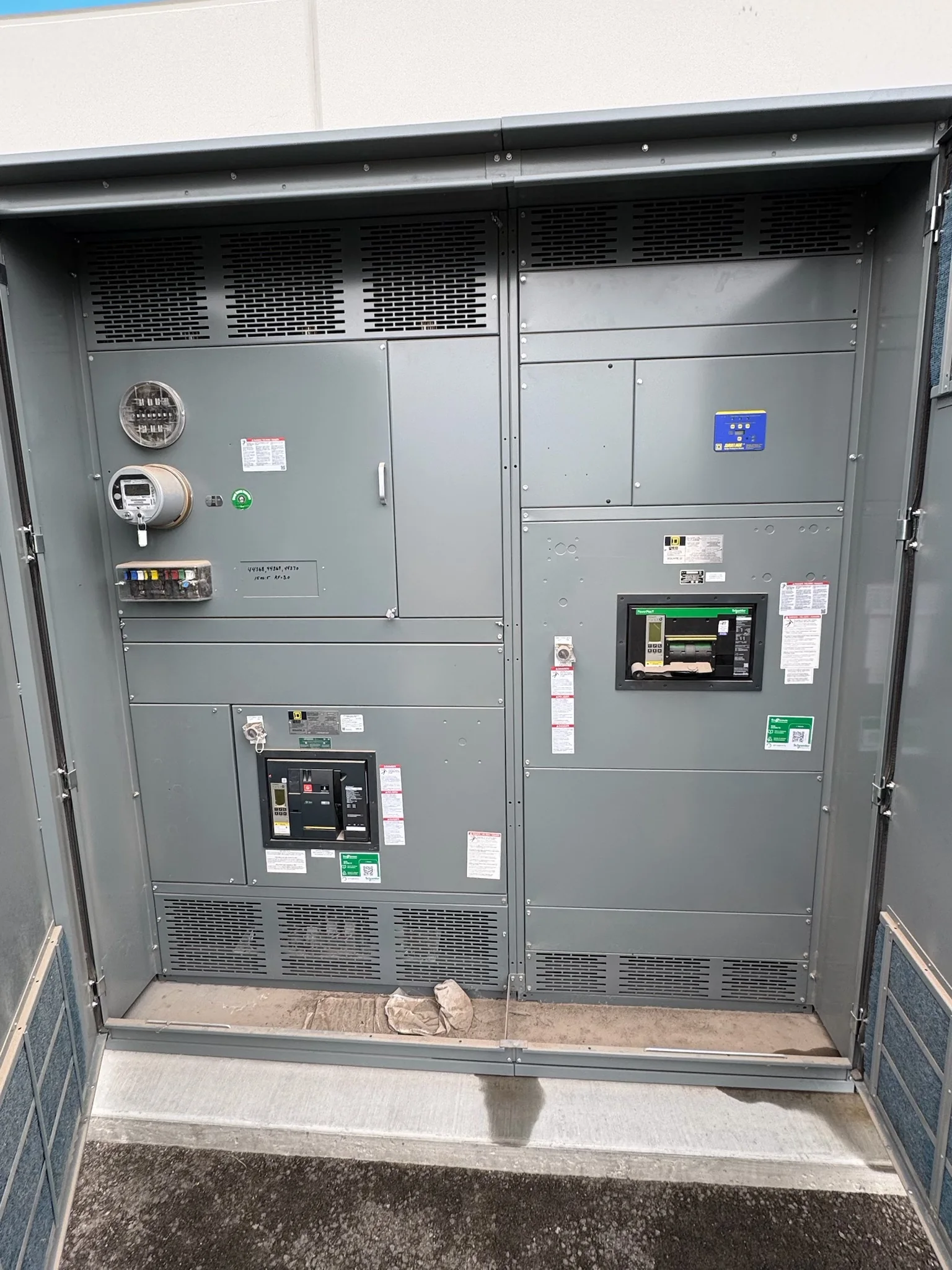
Define the Distribution Scope Before Requesting a Quote
A custom switchgear package starts with the one-line diagram and the job it must perform—not a product name alone. Identify the source and available fault-current information, system voltage, phase and frequency, intended loads, and whether the equipment is a switchboard or another assembly. These details shape bus arrangement, protective-device selection, compartment layout, and connection points. Include existing equipment data when the project is a replacement, but do not assume that a similar nameplate means direct interchangeability. A manufacturer can review the stated requirements and flag missing inputs before the design is finalized. That early alignment matters: unresolved source conditions or load assumptions can affect protection coordination, interfaces, cost, and the installation plan.
Translate Site Conditions Into Buildable Requirements
Room dimensions and operating conditions can change what fits and how the equipment is accessed. Provide available wall and floor space, ceiling height, door and aisle clearances, cable entry direction, and the route from the receiving area to the electrical room. Note ambient temperature, indoor or outdoor exposure, moisture, dust, corrosive agents, and elevation where relevant to the design. These are engineering inputs, not finishing details: an enclosure that suits the electrical ratings may still be impractical if its sections cannot pass through a doorway or if working clearances are constrained. Confirm the applicable codes, project specifications, and authority requirements with the responsible design team. Final suitability and ratings depend on review of the actual application.


Coordinate Protection, Metering, and System Interfaces
Protective devices should be considered in the context of the entire distribution system. Share available fault-current data, upstream and downstream device information, load characteristics, and coordination-study criteria so the project team can evaluate interrupting ratings and protective settings. Identify required metering, control power, alarms, communications, and connection to building or plant systems; state protocols and interface responsibilities where known. A device or communications feature that is assumed rather than specified can leave gaps during commissioning or require late changes. If the equipment will connect to existing gear, document bus, cable, grounding, and control interfaces and have compatibility verified. Device selections, settings, and final ratings are project-specific and should be confirmed by qualified engineering review.
Review Drawings and Submittals Before Release
A useful submittal review checks the equipment against the contract documents and the site—not just whether the model number appears correct. Review the one-line diagram, elevations, general arrangement, connection details, bill of materials, and control schematics as applicable. Verify section lineup, dimensions, access and lifting needs, incoming and outgoing locations, device functions, labels, and any specified accessories. Mark conflicts with the electrical room plan, cable schedule, or installation sequence before approving production. For low-voltage switchboard assemblies, UL 891 may be relevant when required and applicable; it is not a blanket certification for every custom switchgear product or voltage class. Confirm required evaluation, markings, documentation, and acceptance criteria for the specific assembly.
Plan Schedule Around Decisions, Not Assumptions
A short quoted lead time is useful only when its starting point and dependencies are clear. Ask what information is needed to establish the schedule, when drawing approval is required, and how design changes affect release and completion. Custom components, approved device selections, submittal revisions, and unresolved interface questions can influence timing; no delivery date should be treated as firm without project-specific confirmation. For procurement, align the purchase order, approved scope, required documentation, inspection expectations, and requested ship date. If construction is phased, identify which lineup or sections are needed first and whether the arrangement supports the sequence. Early coordination helps expose schedule risk while there is still time to resolve it, rather than after equipment is expected onsite.
Coordinate Freight, Receiving, and Installation Readiness
Nationwide shipping makes delivery planning part of the equipment scope, not an afterthought. Confirm the receiving address, site contact, delivery-hour restrictions, unloading equipment, staging space, and the path from truck to final location. Section dimensions and weights should be reviewed against doorways, turns, elevators, floor capacity, and any rigging limits before shipment is arranged. Protect equipment from weather, impact, and unsuitable storage conditions; establish who will inspect the shipment and record visible damage or missing items. Before installation, verify that the room, grounding provisions, cable routes, and required clearances are ready. Installation, inspection, testing, and energization must follow the approved project documents and applicable safety procedures; de-energized work and qualified personnel are essential.