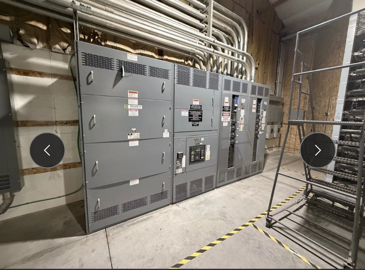
What a Switchgear Lineup Includes
A switchgear lineup is an arrangement of connected electrical sections assembled to control, protect, and distribute power. Depending on the application, sections may contain incoming service equipment, bus, circuit breakers or other protective devices, metering, and outgoing feeder provisions. The lineup is more than a row of cabinets: its sections must work together electrically and fit the building’s power system, operating practices, and available space. A low-voltage switchboard and medium-voltage switchgear are not interchangeable terms, and their construction, ratings, and evaluation requirements differ. Establish the system voltage, source arrangement, fault-current conditions, load needs, and intended use before requesting a quote. Those inputs guide a manufacturer toward a suitable configuration rather than a cabinet arrangement that merely appears to fit.
Start with System Data and Operating Needs
Useful specifications describe both the electrical system and how people will use it. Gather available one-line diagrams, service details, transformer information, fault-current or coordination-study data, and a feeder or load schedule; identify gaps rather than treating estimates as confirmed values. Explain whether operators need metering, particular protective-device functions, source transfer, future feeder capacity, or defined access and maintenance arrangements. These choices affect section layout, wiring, equipment selection, and the information required for review. Also identify the governing project requirements and applicable codes or standards, then have the design team confirm their relevance to the equipment type and jurisdiction. Incomplete or conflicting data can lead to revisions, mismatched connections, or equipment that cannot be approved for the intended installation.


Coordinate the Room Before Finalizing the Layout
A lineup that meets electrical requirements can still create an installation problem if the room is not ready for it. Confirm the available footprint, equipment orientation, access and working clearances, door swing, cable entry and exit paths, overhead obstructions, and the route from the delivery point to the final position. Check floor loading and anchorage requirements with the project’s structural and electrical teams. For indoor installations, consider ventilation, ambient conditions, moisture, dust, and corrosive exposure; outdoor or demanding environments may call for different enclosure considerations. Record constraints on current drawings and flag dimensions that remain unverified. Resolving a narrow doorway, obstructed cable trench, or service-access conflict before fabrication is generally easier than changing the building or equipment after delivery.
Review Drawings and Interfaces Before Release
A coordinated submittal review helps confirm that the proposed lineup connects properly to the rest of the project. Compare the manufacturer’s arrangement and connection information with the one-line diagram, plan views, cable schedules, control requirements, and adjacent equipment interfaces. Verify incoming and outgoing connection locations, phase arrangement, neutral and grounding approach where applicable, metering and control needs, and any specified communication interfaces. Track every comment to resolution and identify who has authority to approve design changes. If existing equipment is involved, provide verified nameplate data, photographs, and connection details; physical and electrical compatibility must be established, not assumed from a similar model name. Approved drawings form an important reference for fabrication, installation planning, and later maintenance, so unresolved exceptions should be documented.
Plan Purchasing, Schedule, and Delivery Together
Requesting a quote early gives the project team time to compare the proposed configuration with its requirements and clarify exclusions, options, and submittal responsibilities. Share the needed-on-site date, approval milestones, site-readiness assumptions, and any phased construction plan, then ask the manufacturer to confirm current timing for the specific scope. Custom construction and component availability can affect the schedule; a general short-lead-time offering is not a guarantee for every lineup. Delivery planning also needs practical detail: receiving hours, unloading equipment, access restrictions, staging space, storage conditions, and who will inspect and take custody. A U.S. manufacturer can coordinate nationwide shipping, but the project should confirm shipment arrangements and responsibilities in writing. Changes to approved requirements may affect both cost and schedule.
Prepare for Installation and Energized Operation
Before shipment, align the installation plan with approved drawings, equipment instructions, applicable project requirements, and the qualified personnel responsible for the work. Confirm foundations, anchorage, conduit and cable routes, grounding provisions, and the sequence for setting and connecting sections. Keep equipment protected from moisture, dust, impact, and unsuitable storage conditions; inspect delivered sections and record damage or discrepancies before installation proceeds. Commissioning plans should address required inspections, testing, protective-device settings, and coordination with upstream and downstream equipment, with responsibilities assigned to qualified personnel. All installation, inspection, maintenance, and troubleshooting must follow safe work practices, including establishing an electrically safe work condition when required; this is not optional. Complete records of approved drawings, settings, test documentation, and maintenance guidance support safer operation and future changes.