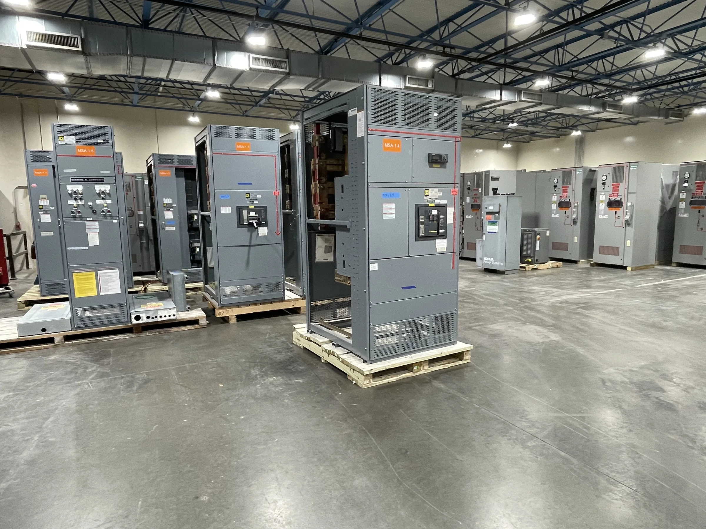
Define the Distribution Need Before Selecting an Assembly
A low-voltage switchgear project in Sugar Land should begin with the electrical system it must serve, not a catalog description. Confirm the service voltage, phase, frequency, available fault current, grounding arrangement, and required continuous current with the design engineer and serving utility. Then map the lineup’s purpose: service entrance, generator paralleling, distribution to large loads, or a combination of functions. These details affect bus design, protective-device selection, metering, and enclosure arrangement. A nominal voltage match alone does not establish compatibility; equipment must suit the actual system and its documented fault-duty requirements. Share the one-line diagram and project criteria early so the manufacturer can identify open questions before they become drawing revisions, procurement delays, or costly field changes.
Coordinate Protection, Loads, and Future Capacity
Protection choices should reflect the loads and operating priorities downstream. Gather load schedules, motor-starting information, transformer data, and any requirements for selective coordination or arc-energy reduction from the project team. An engineer can use those inputs to develop and verify a protective-device scheme; a manufacturer should not infer settings or coordination from the service rating alone. Also distinguish installed capacity from space reserved for future circuits. Spare sections or provisions may affect lineup length, bus arrangements, and the building footprint, while unused circuit positions do not automatically mean future expansion will be straightforward. In Sugar Land facilities with changing production, tenant, or building-service needs, documenting planned growth now can help the team compare initial cost against later outage, construction, and replacement impacts.


Match the Lineup to the Electrical Room
Room dimensions and access paths can determine whether a technically suitable lineup can actually be installed. Provide clear room plans, equipment elevations, door and corridor widths, ceiling height, floor elevations, and the intended cable-entry direction. The team should check working clearances and access requirements against applicable codes and the project design, including space for opening doors, operating devices, inspection, and maintenance. Consider where conduits and bus connections enter, and whether overhead services conflict with lifting or assembly. Sugar Land projects may also involve occupied commercial buildings, industrial sites, or additions beside existing electrical rooms; each creates different staging and outage constraints. Confirm route and installation assumptions before drawings are approved, because a tight turn or obstructed entrance can force a costly change in the field.
Plan for Gulf Coast Heat, Humidity, and Exposure
Environmental conditions deserve specific review rather than a generic indoor or outdoor designation. Identify the equipment location, expected ambient temperature, ventilation, humidity, dust, washdown exposure, and any corrosive or otherwise unusual conditions. High heat can affect allowable loading and equipment cooling, while moisture or contaminants can influence enclosure and component choices. If the lineup will sit outdoors, near a loading area, or in a process space, describe the exposure and required enclosure conditions for project-specific evaluation. Sugar Land’s Gulf Coast setting makes it sensible to discuss seasonal humidity, heavy rain, and storm-related site access with the design and construction teams, without assuming one enclosure choice suits every installation. Verify environmental assumptions, room conditions, and any mitigation measures before finalizing the specification.
Review Drawings, Interfaces, and UL 891 Scope
A useful submittal review checks more than overall dimensions. Compare the manufacturer’s drawings with the approved one-line diagram, feeder schedule, control schematics, cable landing space, metering requirements, and interface points for generators, transfer equipment, building controls, or other systems. Resolve who supplies each connection and signal, and record terminal or communications requirements where applicable. Ask which documents will be provided for review, what information the manufacturer needs to release approved drawings, and how revisions will be handled. UL 891 applies to appropriately evaluated low-voltage switchboard assemblies; it is not a blanket certification for every equipment type or configuration. Confirm the specified assembly’s evaluation and labeling requirements for the project rather than assuming that a standard reference covers every component or application.
Align Manufacturing, Delivery, and Site Readiness
Discuss schedule and delivery as project variables, not as a promised number of weeks. Confirm the current drawing-approval path, submittal review duration, component availability, requested ship window, and any dependencies that could change the sequence. A U.S. manufacturer can discuss custom construction, American components, short lead times, and nationwide shipping, but the actual schedule and component selection depend on the approved design and availability. For a Sugar Land delivery, coordinate receiving hours, truck access, unloading equipment, staging space, weather protection, and the route from the receiving point to the electrical room. Establish who accepts and inspects the shipment and where it can be stored if installation is not immediate. Before energization, qualified personnel must complete required installation checks and commissioning under the project documents and applicable requirements.