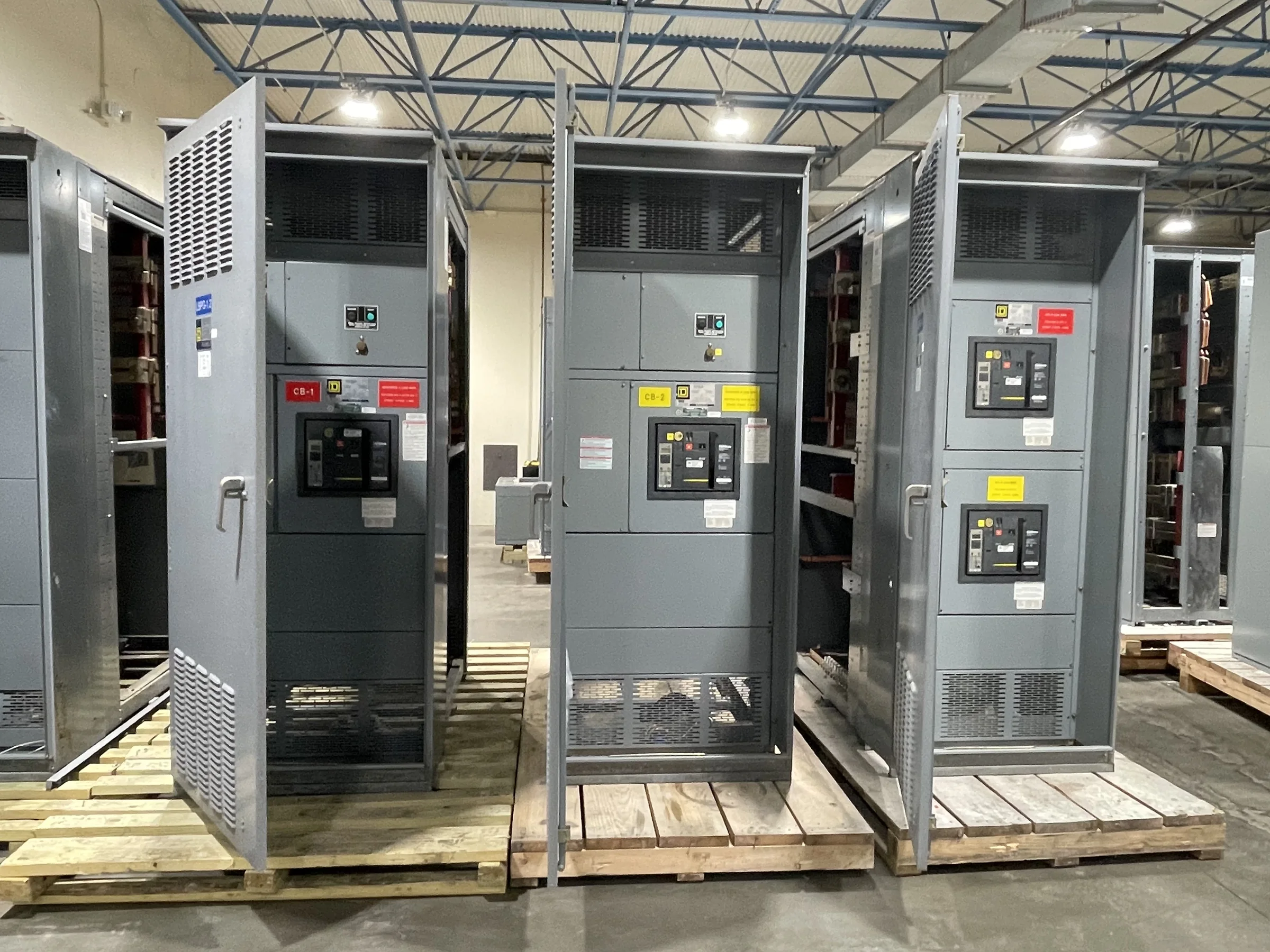
Define the Conroe Application Before Selecting Equipment
Medium-voltage switchgear selection starts with the facility’s distribution plan, not a catalog label. Document the utility service arrangement, nominal system voltage, available fault current, grounding method, incoming and outgoing feeders, and the loads each section must serve. These details influence bus design, protective-device selection, compartment arrangement, and the space needed for cable terminations. In Conroe, a project may serve manufacturing, water-related infrastructure, commercial development, or another load profile; the equipment must reflect the actual site rather than a broad regional assumption. Ask the engineer of record and serving utility to confirm interface requirements early. A U.S. manufacturer can then develop a new assembly around the approved project criteria, while ratings, applicable standards, and design feasibility remain subject to engineering review.
Coordinate Protection, Controls, and Utility Interfaces
Protection choices affect both safety and continuity, so specify more than breaker quantity. Share the one-line diagram, protection philosophy, relay functions, metering needs, control power, communications requirements, and any required interlocks. Confirm which devices and settings are furnished by the equipment manufacturer and which are supplied or approved by the utility, engineer, or controls contractor. In particular, relay coordination depends on verified system data and the protection study; it should not be inferred from a typical application. Agree on terminal points and signal responsibilities before drawings are released, since unclear ownership can create late wiring changes or commissioning delays. The final scheme should be reviewed by qualified project professionals for the specific system. Equipment configuration, device compatibility, and testing scope are project-specific.


Check the Building and Electrical Room Constraints
A technically suitable lineup still has to fit the site and be maintainable after installation. Provide room plans and elevations showing doors, columns, ceiling height, trenches, overhead services, cable entry direction, and the intended equipment route from receiving to the final position. Identify required working clearances and access for inspection, operation, and future component removal; have the responsible design team confirm applicable code and project requirements. Conroe-area facilities may also need to coordinate delivery with active plant traffic, security procedures, construction sequencing, or limited staging space. Those conditions affect shipping splits, rigging plans, unloading equipment, and the date the room must be ready. Confirm floor loading and anchorage with the project’s structural professionals. Do not assume a standard footprint or shipping configuration will suit the building.
Resolve Environmental and Installation Conditions
The installation environment can change equipment requirements even when the electrical ratings appear straightforward. Describe indoor or outdoor placement, ambient conditions, ventilation, dust or moisture exposure, corrosive agents, elevation where relevant, and any project-specific enclosure or finish needs. For a Conroe site, discuss exposure to humid Gulf Coast conditions and seasonal severe weather with the project engineer; actual exposure varies by location and installation. Also clarify whether the switchgear room is conditioned and how condensation, drainage, and water intrusion are addressed. These facts help the manufacturer assess a suitable configuration, but they do not establish a guaranteed enclosure rating or environmental capability without review. Specify who handles foundations, conduits, cable pulling, grounding, and field connections. Installation and acceptance should follow approved documents and be performed by qualified personnel with equipment de-energized.
Build a Complete Submittal and Procurement Package
A clear request for quotation helps the manufacturer identify omissions before they become schedule or scope disputes. Include the latest one-line and three-line diagrams, equipment layout, load and fault information, utility criteria, relay and metering schedules, control schematics, cable data, applicable project standards, and required submittal formats. State whether the scope includes engineering drawings, factory inspection or testing, manuals, spare parts, or field support, and identify exclusions explicitly. Ask for a proposed bill of material and a compliance or exception list so reviewers can compare the offer against the specification. If a replacement or retrofit is planned, provide existing nameplate information, dimensions, connection details, and outage constraints; compatibility must be checked rather than presumed. Requirements, standards, testing, and any applicable approvals are confirmed for each project.
Plan Timing, Delivery, and Commissioning Together
Discuss the schedule while the design is still being defined, not after the room and outage dates are fixed. Ask the manufacturer to review drawing approval milestones, long-lead components, customer-furnished items, inspection requirements, shipping configuration, and dependencies that could affect the requested delivery window. Short lead times may be available for suitable builds, but no duration should be treated as guaranteed until scope, components, approvals, and current availability are confirmed. For delivery to Conroe, coordinate the receiving address, site access, carrier restrictions, unloading responsibility, staging area, and whether the shipment can reach the electrical room or only the facility dock. Tie shipment release to room readiness and installation planning. Before energization, qualified personnel should complete required inspections, protection checks, and commissioning under the approved project procedures.