Define the Distribution Role Before Selecting an Enclosure
Pad-mounted switchgear is typically selected for an outdoor distribution point where access, switching functions, and equipment protection must work together within a compact footprint. Start by documenting the system voltage, available fault current, grounding method, feeder count, and the switching or protective functions required at each way. These details influence equipment configuration and help prevent a quote based on an arrangement that cannot serve the intended operating plan. Clarify whether the installation is new, replaces existing gear, or connects to a broader utility or facility system; interfaces and acceptable interruption windows may differ. A U.S. manufacturer can build around project requirements, but final ratings, construction, and any applicable evaluation must be confirmed for the specific assembly. Treat the one-line diagram as a design input, not a substitute for coordination.
Coordinate Switching Functions With the Protection Scheme
The number and purpose of ways should follow the electrical operating sequence, not simply the available space on a drawing. Identify which circuits must be isolated, transferred, protected, or reserved for future use, then review those needs with the engineer responsible for the protection and coordination study. Fuse selection, relay functions, sensing, and interrupting requirements depend on system conditions and equipment design; none should be assumed from a product name alone. The control scheme also matters: operators need clear device identification and a defined method for confirming equipment status before switching. Where the installation interfaces with utility equipment, agree on responsibilities, approved arrangements, and connection details early. That review reduces late drawing changes and helps ensure the delivered configuration supports the intended operating procedure without implying that energized work is acceptable.


Check the Site Envelope and Underground Interfaces
A pad-mounted assembly can fit its electrical footprint and still be difficult to install or service if the site plan omits access and underground details. Confirm the proposed pad dimensions and placement against the project drawings, while accounting for door swing, working access, vehicle exposure, drainage, and the route needed to position the equipment. Civil and electrical teams should reconcile conduit entry locations, duct-bank geometry, cable bend space, and grounding provisions before concrete is placed. Soil conditions, water exposure, contaminants, and expected ambient conditions may affect enclosure and finish decisions, so document the actual site environment rather than relying on a generic outdoor assumption. Required clearances and access provisions are project-specific and should be checked against applicable codes, utility requirements, and manufacturer drawings. Resolving these constraints early helps avoid costly field rework.
Build a Quote Package That Supports Accurate Review
A useful request for quotation gives the manufacturer enough information to distinguish required functions from preferences. Include the current one-line diagram, equipment schedule, system data, required switching and protection functions, interface requirements, and the project’s applicable standards or utility criteria. Provide site and cable-entry information when available, plus any specified enclosure, labeling, finish, or control preferences. Mark open engineering items clearly instead of presenting assumptions as approved requirements. Ask for a proposed configuration, a list of deviations or clarifications, and the drawings and submittals expected for review. This makes commercial comparisons more meaningful: a lower initial price may reflect omitted functions, unresolved interfaces, or a different scope. Ratings, compatibility, evaluation status, and availability must be confirmed for the proposed assembly and application; they should not be inferred from a general product description.
Plan Schedule Around Engineering, Approvals, and Site Readiness
A short manufacturing lead time can support a project schedule, but the actual timing depends on the approved configuration, component availability, drawing review, and release of required information. Establish the date when complete project inputs are needed, who has authority to approve submittals, and how quickly comments will be returned. Track engineering approval separately from the purchase order and from site readiness; these milestones are related but not interchangeable. If the installation depends on an outage, contractor mobilization, or a utility witness, coordinate those dates against the confirmed equipment schedule rather than an early estimate. Custom construction can address project requirements, yet late changes to ratings, controls, cable interfaces, or dimensions may require renewed review. Ask the manufacturer to confirm current timing and identify schedule assumptions in writing before committing dependent work.
Coordinate Delivery, Receiving, and Closeout Records
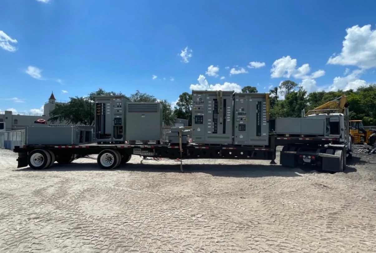
Nationwide shipping does not remove the need for a receiving plan. Confirm the delivery address, access restrictions, unloading responsibility, lifting arrangements, staging area, and whether the site can accept the equipment on the scheduled date. A constrained industrial yard, active loading dock, or unfinished pad may require coordination among the carrier, electrical contractor, and site team; missing equipment or access can create storage costs and delay installation. Before shipment, reconcile approved drawings with the purchase scope and confirm the documentation required for installation, operation, maintenance, and project closeout. On receipt, inspect the shipment and record visible damage or discrepancies promptly under the applicable shipping process. Preserve approved submittals, final equipment identification, and any project-specific test or evaluation records supplied for the assembly. Final acceptance and connection must follow the project’s safety procedures and qualified personnel’s review.