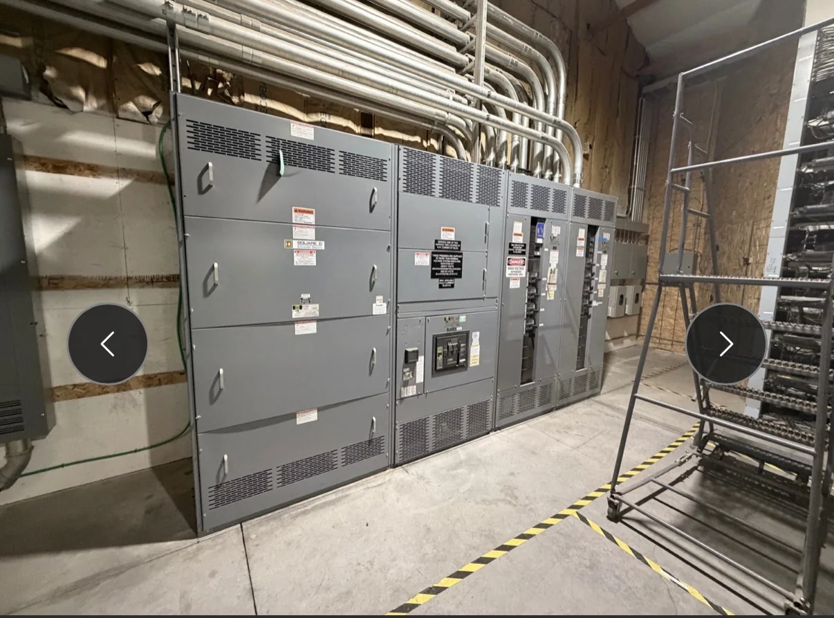
Match Switchgear to the Plant’s Electrical Architecture
Power plant switchgear must fit the one-line diagram, operating philosophy, and equipment it serves—not simply match a voltage class. Engineers should identify generator connections, auxiliary buses, transformers, station-service sources, tie breakers, and any normal or alternate feeds that affect the lineup. Fault-current levels, grounding method, continuous load, and required interrupting or withstand ratings need to be established for each application. These inputs influence bus arrangement, protective devices, compartment design, and coordination with upstream and downstream equipment. A mismatch can create protection gaps or prevent the assembly from integrating with existing gear. Provide the manufacturer with current drawings and study assumptions early; final ratings, construction, and compatibility remain subject to project-specific engineering review.
Define Operating Modes and Protection Interfaces
A plant’s switchgear may support generation, startup, shutdown, standby, and maintenance conditions, each with different sources and load paths. Document which breakers may close together, how transfers are initiated, and what interlocks or control signals must be preserved. Protection requirements should be coordinated with the plant’s short-circuit and coordination studies, including relay functions, instrument-transformer needs, trip circuits, and interfaces to supervisory controls. Existing relay settings or control schemes should not be assumed to transfer unchanged to replacement equipment. Clear interface schedules help identify wiring, communications, and terminal requirements before fabrication. This detail matters because an electrically suitable lineup can still disrupt plant operation if its controls, protection, or sequence logic do not match the approved operating philosophy.


Plan Around Environment, Access, and Maintainability
The installation area can shape the equipment arrangement as much as the electrical design. Confirm indoor or outdoor exposure, ambient conditions, elevation, contamination, ventilation, seismic or other project criteria, and available working clearances with the design team. In a generating station, cable trenches, overhead services, structural steel, fire barriers, and adjacent operating equipment may constrain lineup dimensions and entry points. Record the route from receiving area to final position, including door openings, turns, floor capacity, lifting access, and whether sections must be handled separately. These checks reduce the risk of equipment arriving that cannot be moved into place or connected as intended. Also consider safe access for inspection and maintenance when choosing doors, compartments, and cable termination locations.
Prepare a Complete, Reviewable Procurement Package
A useful request for quotation gives suppliers enough information to identify scope and flag unresolved decisions. Include the one-line diagram, equipment schedule, applicable project specifications, load and fault data, grounding details, control schematics, cable requirements, and drawings of the installation area. Identify interfaces with transformers, generators, protective relays, existing switchgear, and plant control systems. State the required submittal and approval process, inspection expectations, document format, and any project-specific standards or exceptions. Mark information that is preliminary so it is not mistaken for a released design basis. A complete package helps compare equivalent scope rather than headline price alone, while early clarification of omissions can prevent redesign, added coordination, or a procurement schedule built around unconfirmed assumptions.
Coordinate Schedule, Reviews, and Delivery
Project timing depends on the approved design, component selection, review cycles, and site readiness; a requested ship date should be treated as a planning target until scope and availability are confirmed. Establish who will review drawings, how comments are resolved, and when the manufacturer needs released information to proceed. Align delivery planning with construction sequencing, outage windows, receiving capacity, and storage conditions. Confirm shipment configuration, unloading responsibility, site contact, access hours, and whether equipment can be received and protected before the electrical room is ready. For multi-section lineups, agree on identification and delivery order so crews can place equipment efficiently. A U.S. manufacturer can discuss custom build options, American components, short lead times, and nationwide shipping, with specifics verified for each project.
Verify Standards, Documentation, and Replacement Scope
Specify the standard and evaluation requirements that apply to the actual equipment, rather than using a broad label for an entire plant lineup. UL 891 may apply to appropriately evaluated low-voltage switchboard assemblies; it is not a blanket certification for medium- or high-voltage switchgear. Confirm applicable ratings, construction, labeling, and documentation for each assembly with the project engineer and manufacturer. For replacement or retrofit work, record existing enclosure dimensions, bus and cable interfaces, protection devices, control wiring, and any operating constraints that must be maintained. Request drawings and other agreed project documents for review before release. This is important because physical fit alone does not establish electrical compatibility, code acceptance, or suitability for the plant’s duty; those determinations depend on the specific design and evaluation.