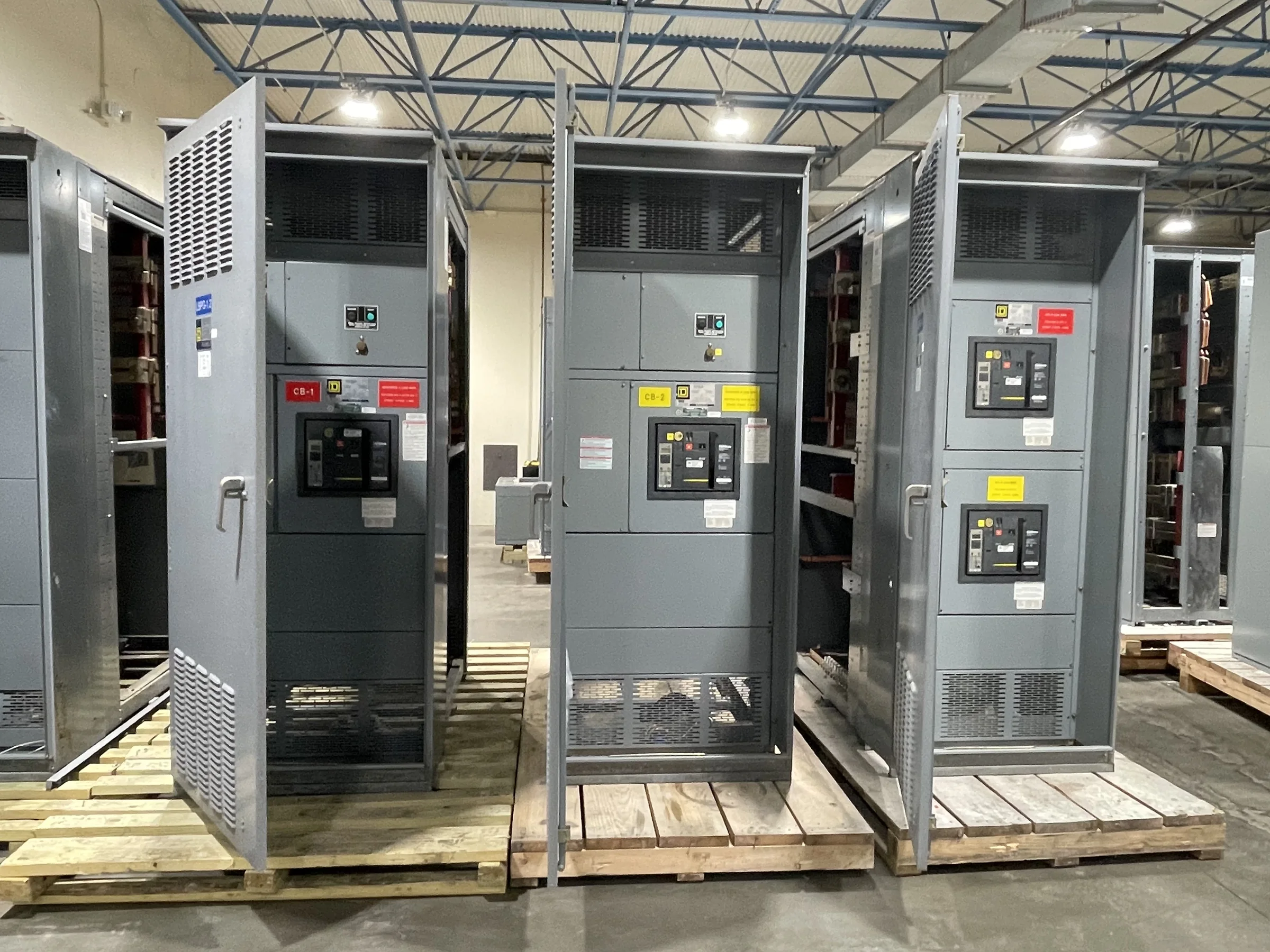
Define the Replacement Boundary Before Selecting Equipment
In La Porte, a switchgear replacement can involve a single distribution section, a complete lineup, or equipment feeding several process areas. Establishing the boundary early helps prevent a quote from overlooking connected loads, protective devices, metering, or transition work. Document the existing equipment’s manufacturer, model, voltage, phase, wire configuration, bus ratings, interrupting requirements, enclosure details, and available nameplate information; have qualified personnel verify field conditions. Include one-line diagrams and identify upstream and downstream equipment, alternate sources, and any ties. These details let the manufacturer evaluate a new assembly against the actual application instead of assuming the old lineup’s dimensions or ratings tell the whole story. Final design, compatibility, and applicable standards must be confirmed for the specific project.
Specify Electrical Performance, Not Just a Physical Match
A replacement lineup must suit the system’s electrical duty as well as the space it occupies. Provide available fault-current information, source and transformer data, grounding method, load characteristics, and the required protective-device functions. Confirm whether the project needs main, feeder, tie, metering, or control provisions, and identify coordination or arc-flash studies that inform device selection. A physically similar cabinet does not establish that its bus, breaker ratings, or protection are appropriate for the installation. Where existing study data are unavailable or conditions have changed, flag that gap for the project engineer to resolve before equipment is released for manufacture. Ratings, device coordination, and any applicable evaluation or listing are specific to the assembly and project; they should not be presumed from a general product description.


Coordinate Dimensions, Access and Removal at the Site
La Porte facilities may have congested electrical rooms, adjacent process equipment, pipe racks, or limited staging and rigging access. Record room and doorway dimensions, equipment orientation, working clearances, overhead obstructions, cable-entry locations, and the route from unloading point to final position. Photograph the lineup and surrounding conditions, then compare measurements with current drawings; legacy drawings may not reflect later modifications. Check whether the replacement can be installed in the existing footprint or whether foundation, conduit, busway, cable, or enclosure changes need engineering review. Access constraints affect section arrangement, shipping configuration, lifting plans, and outage duration, so raising them during specification review can avoid costly field changes. A qualified site team should validate measurements and plan safe removal and installation under the facility’s procedures.
Plan the Outage and Transition Around Operations
For an industrial site in La Porte, a switchgear outage may affect production systems, utilities, environmental controls, or other loads that cannot simply be interrupted on a convenient day. Identify critical loads, shutdown dependencies, standby sources, temporary-power constraints, and the facility’s approval process before choosing a transition strategy. Ask the project team to define which equipment must be isolated, what work can occur before the outage, and what inspections or commissioning checks are required before re-energization. New equipment can be built to project requirements, but manufacturing time is only one part of the schedule: engineering approvals, site preparation, shipping, removal, installation, and testing also matter. Treat dates as planning targets until scope, drawings, materials, and site readiness are confirmed; never rely on energized work as a substitute for planned de-energization.
Prepare a Complete Quote and Submittal Package
A useful request for quote gives the manufacturer enough information to identify open technical questions instead of pricing an assumed configuration. Include the one-line diagram, equipment schedule, existing nameplate photographs, preliminary layout, load and fault-current data, preferred components where specified, and required control or metering functions. Note environmental conditions, enclosure needs, cable or bus connections, interface requirements, and any governing project specifications. Identify whether the project concerns a low-voltage switchboard assembly or medium-voltage equipment; UL 891 applies to appropriately evaluated low-voltage switchboard assemblies, not as a blanket certification for every voltage class or product. During review, compare the proposed scope with the bid documents and request clarification on exclusions, engineering submittals, testing, and documentation. Exact compliance and labeling depend on the final design and evaluation.
Coordinate Delivery, Documentation and Final Acceptance
Nationwide shipping can support a La Porte replacement, but delivery planning should be tied to site access and the installation sequence rather than treated as a final logistics detail. Confirm the receiving contact, delivery hours, truck and unloading access, staging space, weather protection, and any limits on storing equipment before installation. Align the shipping configuration and arrival window with the contractor’s handling plan and the facility’s outage approvals. Before release, track drawing review, approved deviations, interface dimensions, and any project-specific test or documentation requirements. At handover, the facility team should receive the records required by the contract, which may include final drawings, device information, operating instructions, and test documentation where applicable. Review completeness and condition on arrival, and resolve discrepancies with the project team before installation or acceptance.