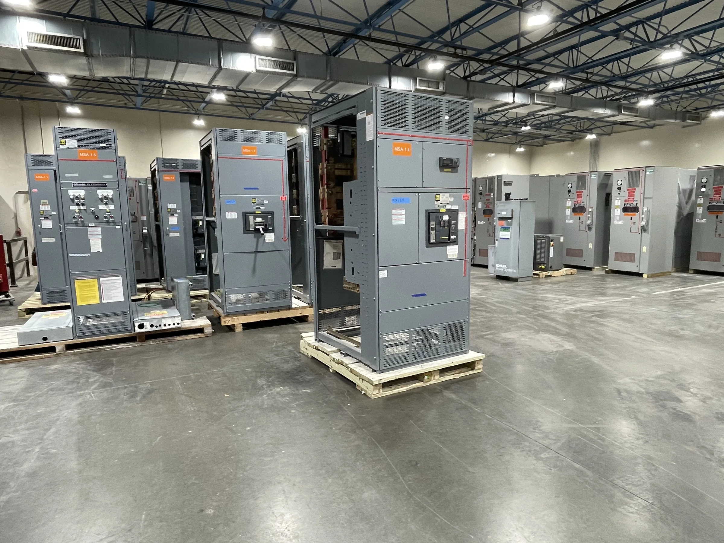
How to Read a Switchgear Specification
A switchgear specification is the project’s shared definition of what the equipment must do, where it will connect, and how it will be accepted. Start with system voltage, phase, frequency, available fault current, continuous load, and the required short-circuit or withstand ratings; each value affects equipment selection and coordination. Identify the service entrance, feeder arrangement, grounding method, and whether the design is intended for a new installation or a replacement. Then confirm applicable codes, owner standards, and any required evaluation or labeling. For low-voltage switchboard assemblies, UL 891 may be relevant when the assembly is appropriately evaluated; it is not a blanket certification for medium- or high-voltage equipment. Resolve omissions before quotation, because assumptions can change design, price, and schedule.
Ratings, Interrupting Duty, and Coordination
Several ratings that sound interchangeable describe different limits. Nominal voltage identifies the system class, while continuous-current rating addresses the load the equipment is designed to carry under stated conditions. Short-circuit and interrupting ratings relate to fault conditions, but their meaning depends on the assembly, protective devices, and applicable standards. Ask the engineer to document the calculated available fault current at the equipment location and the protection scheme, rather than selecting a rating by matching an upstream device alone. Selective coordination may also influence breaker types, settings, and the time-current study. These choices matter because an inadequately rated assembly can create a serious safety and compliance problem, while an unnecessarily high rating may affect cost and dimensions. Confirm final values with the project engineer and manufacturer.


Lineups, Sections, and Bus Arrangements
A lineup is the connected arrangement of equipment sections that serves the distribution plan; its configuration determines how circuits enter, pass through, and leave the assembly. Glossary terms such as main breaker, main lugs, tie breaker, and feeder breaker describe functional positions, not universal layouts. A normally open tie, for example, may support an alternate source arrangement, but operating logic and interlocks must be defined in the approved design. Bus ratings and material, section sequence, cable access, and future provisions also affect the build. Provide a one-line diagram and elevation with source locations, loads, metering, and required compartments. Clear documentation helps the manufacturer identify conflicts early, while vague labels or assumed interchangeability can lead to redesign or field connection problems.
Replacement, Retrofit, and Existing Conditions
Replacing existing gear is not simply a matter of matching its nameplate. Record the installed manufacturer and model, dimensions, bus orientation, conductor entry, connection points, mounting details, and available working space. Photograph nameplates and the full installation, and obtain existing drawings when available; field conditions may differ from old records. The replacement design must also be checked against present system conditions, including fault duty, protection, grounding, and connected loads. A retrofit may preserve some existing infrastructure, but mechanical fit and electrical compatibility must be established rather than assumed. These checks matter because a small mismatch in footprint, bus interface, or cable bend space can disrupt installation and extend an outage. Have qualified personnel verify site information with equipment de-energized under the facility’s safety procedures.
Submittals, Drawings, and Approval Hold Points
Submittals turn procurement requirements into a reviewable equipment design. A useful package may include outline and elevation drawings, one-line diagrams, component schedules, connection details, ratings, and requested test or compliance documentation, as applicable to the project. Review dimensions, access, conduit or cable entry, lifting provisions, and field termination space—not only electrical symbols. Compare the submittal against the specification and identify deviations explicitly, including any component substitutions or unresolved selections. Approval should come from the parties responsible for engineering and facility acceptance before fabrication proceeds. This hold point matters because late changes to breaker arrangements, metering, or enclosure details can affect both cost and timing. Keep a controlled record of revisions so procurement, the electrical contractor, and commissioning team are working from the same approved design.
Lead Time, Shipping, and Site Readiness
Lead time begins with a complete, reviewable scope, but the actual schedule depends on project requirements, design approvals, component availability, and manufacturing conditions. Request a project-specific schedule and clarify which submittal approvals or customer decisions affect it; a stated estimate should not be treated as a guaranteed delivery date. For shipment, confirm the receiving address, unloading equipment, delivery access, appointment rules, storage plan, and who inspects the equipment on arrival. Large sections may have weight, dimension, or orientation limits that affect doors, corridors, slabs, and rigging routes. Planning these constraints early matters because equipment that reaches the site before its room is ready can be exposed to damage or create costly storage and handling needs. Coordinate delivery sequencing with construction milestones and the planned outage or cutover window.