Define the Modernization Scope Before Selecting Equipment
In Katy, a switchgear modernization project may involve replacing an aging assembly, adding capacity for new loads, or coordinating equipment changes with a broader facility upgrade. Those scopes require different decisions, so begin with a verified one-line diagram, current equipment nameplates, load information, and a clear description of what must remain in service. Identify the existing system voltage, available fault-current data, grounding arrangement, protective-device requirements, and connection points; confirm uncertain details with the project engineer. A new lineup can be built around project requirements, but compatibility with existing conductors, bus connections, protection schemes, and space cannot be assumed from a photograph or legacy drawing. Resolving these items early helps the design team identify interfaces, avoid scope gaps, and prepare a quote that reflects the actual installation.
Match Ratings and Protection to the Electrical Study
Equipment ratings should follow the project’s documented electrical conditions, not a general preference for a larger number. The engineer of record should establish applicable voltage, continuous-current needs, short-circuit withstand or interrupting requirements, and protective-device coordination using the system study and governing project criteria. Confirm whether the modernization changes utility service, transformer capacity, generator operation, or parallel sources, since each can affect available fault current and protection settings. Katy facilities with changing production loads may also need space or provisions for planned circuits, but future expansion should be defined rather than assumed. Review metering, control power, interlocking, and communications requirements alongside the power design. Final ratings, device selections, standards, and any evaluation or listing are specific to the assembly and application; verify them against approved submittals before authorizing manufacture.


Plan Outage Boundaries and Replacement Interfaces
The installation plan often determines whether a technically suitable lineup can be put in place without avoidable disruption. Document which loads require continuity, what outage windows are available, and whether temporary power is part of the project scope. Electrical work must be performed under the site’s approved safety procedures; equipment being replaced must be de-energized, isolated, and verified before work begins. Record the existing cable entry direction, conductor material and size, termination space, bus arrangement, neutral and ground connections, and room access. These details matter because a replacement that fits the electrical schedule may still conflict with installed conduits, structural members, or working clearances. Field verification by qualified personnel, coordinated with the responsible engineer and installer, helps expose interface issues before the new equipment is released for manufacture.
Check the Katy Site, Route, and Receiving Plan
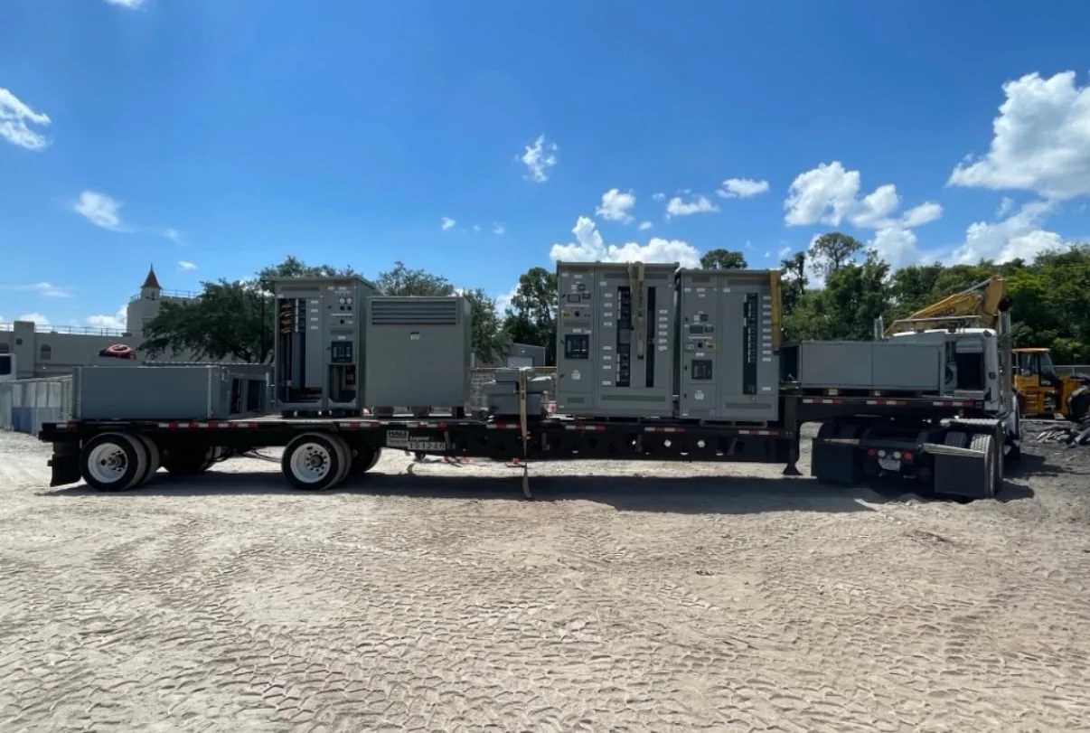
Katy’s mix of commercial, industrial, and growing development areas makes site access and receiving details worth confirming early, especially when equipment is destined for an active facility. Provide the manufacturer with the delivery address, receiving hours, unloading capability, staging limits, and any gate, dock, escort, or vehicle restrictions. Confirm the planned route from the receiving point to the electrical room, including door openings, turns, floor transitions, and available handling equipment. A lineup’s shipping sections and dimensions must be considered alongside the final room layout and installation sequence; do not assume a single shipment can be moved directly into place. Nationwide shipping can support projects in the area, but carrier arrangements, packaging, shipment configuration, and delivery timing depend on the approved equipment and site conditions. Coordinate responsibilities with the installer and site contact.
Use Submittals to Resolve Design and Procurement Questions
A complete submittal review gives the engineer, facility team, and purchasing group a common basis for approving the build. Request drawings and schedules that identify the proposed lineup arrangement, dimensions, ratings, devices, metering, control features, and points of connection. Compare them with the one-line diagram, specifications, room plan, cable schedule, and project-specific standards, then return consolidated comments through the designated approval process. Clarify deviations, exclusions, owner-furnished items, and responsibility for field connections before releasing the order. If a low-voltage switchboard assembly is specified to UL 891, confirm that the particular assembly is evaluated and labeled as required; the standard is not a blanket certification for medium- or high-voltage equipment. Treat component origin, availability, and substitutions as procurement questions to verify for the selected configuration, not assumptions about every build.
Coordinate Build Timing, Delivery, and Handover
Discuss the required in-service date with the manufacturer while the scope and submittal package are being developed. Custom configurations, component selection, drawing review, approvals, and shipping arrangements can affect the project schedule, so request a current, project-specific timing assessment rather than relying on a general short-lead-time expectation. Agree on drawing milestones, approval responsibilities, change-control procedures, shipment readiness, and who will coordinate receiving and installation. Before turnover, collect the approved drawings, equipment schedules, applicable operation and maintenance information, and any project-required test or inspection records. Confirm that final settings, labels, and field connections are handled by the responsible qualified parties in accordance with the approved design. A U.S. manufacturer can discuss new equipment built around the project and delivery to Katy; final configuration, documentation, availability, and timing remain subject to project review and approval.