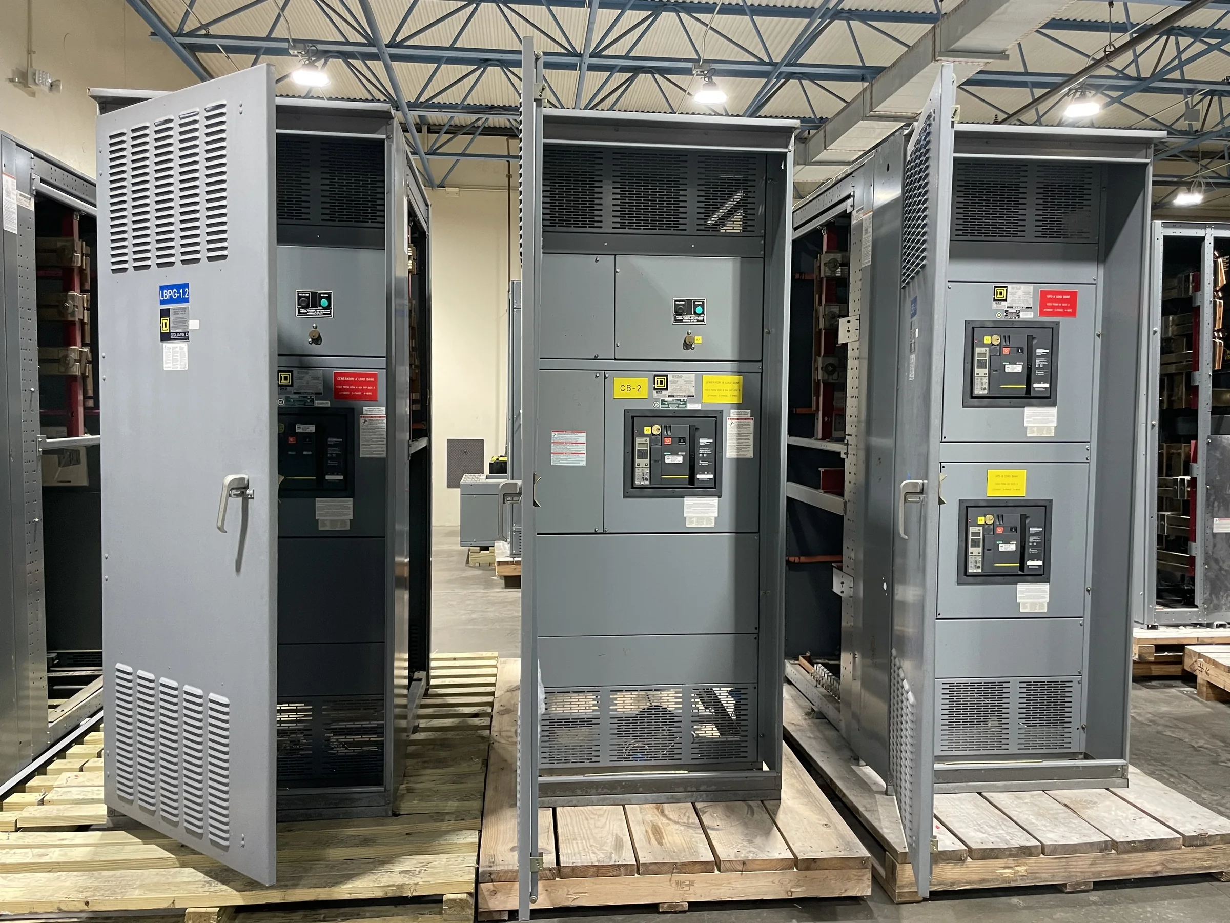
Define the Replacement Scope Before Selecting Equipment
A replacement project in Conroe starts with identifying what the existing switchgear actually serves, not simply matching its nameplate. Record the system voltage, phase, frequency, available fault-current information, service configuration, bus arrangement, breaker types, and connected loads; have qualified personnel verify field conditions and drawings. Note whether the equipment is a low-voltage switchboard, switchgear lineup, or medium-voltage assembly, because those categories have different design and evaluation requirements. Also identify the reason for replacement: capacity constraints, deteriorated components, operational changes, or a planned facility upgrade may point to different solutions. A precise scope reduces the risk of quoting an incompatible lineup and gives the manufacturer a sound basis for discussing configuration, project-specific standards, and the information still needed.
Check Electrical Compatibility and Protection Requirements
Electrical compatibility involves more than matching nominal voltage and amperage. Engineers should review the system one-line diagram, grounding method, source and tie arrangements, load-flow assumptions, and the available short-circuit current at the equipment location. That fault-current value affects equipment selection and protective-device coordination; it should come from a current, project-appropriate study or be confirmed by the responsible engineer and utility information where applicable. Document breaker frame and trip requirements, selective-coordination goals, metering, control power, and any interface with generators, transformers, or automatic transfer equipment. For low-voltage switchboard assemblies, UL 891 may be relevant when the assembly is appropriately evaluated for the application; it does not establish a blanket listing for every product or for medium-voltage equipment. Confirm evaluation, ratings, and project standards for the specific design.


Measure the Site and Plan the Changeover
A replacement lineup must fit the room and the route into it, not just the electrical schedule. Measure available width, depth, ceiling height, anchorage, housekeeping pads, working clearances, and access to doors, corridors, loading areas, and elevators. Compare those measurements with the proposed shipping sections, lifting points, and assembly approach before approving a layout. In Conroe, coordinate delivery around the facility’s operating schedule, site access rules, receiving capacity, and any weather-sensitive unloading plan; do not assume a truck can reach the equipment room. The changeover also needs a documented outage window, temporary-power decision where necessary, and an approved sequence prepared by qualified personnel. These checks matter because late discoveries can disrupt production, force layout revisions, or leave equipment waiting in an unsuitable staging area.
Prepare the Information Needed for a Useful Quote
A clear request for quotation helps the manufacturer distinguish firm requirements from open design questions. Provide the one-line diagram, existing equipment photographs, dimensions, schedules, applicable specifications, breaker and accessory lists, and available short-circuit or coordination study information. Identify the project location in Conroe, requested ship-to conditions, unloading responsibilities, required submittal documents, and the date by which the facility needs equipment on site. State which components must be American-made or American-sourced, if that is a project requirement, and ask how the proposed configuration addresses it. Separate mandatory criteria from preferences so alternatives can be evaluated without obscuring compliance gaps. Pricing, product availability, manufacturing duration, and shipping arrangements depend on the approved design and current project conditions, so request confirmation rather than relying on an assumed lead time.
Review Submittals, Interfaces, and Documentation
Before releasing a build, compare the submitted drawings and schedules against the project specification and verified field measurements. Check lineup dimensions, compartment arrangement, bus connections, cable entry, breaker designations, control wiring, metering, labels, and interfaces with existing transformers or downstream distribution. Confirm that the one-line diagram and equipment schedules reflect the intended source configuration and that discrepancies are resolved by the responsible engineer. For a retrofit, document which existing conductors, conduits, control circuits, and protection devices are expected to remain; apparent physical fit does not prove electrical or mechanical compatibility. Ask for the project-specific documentation required for review, installation planning, and turnover, including applicable evaluation information. Thorough review matters because a drawing mismatch found before manufacture is generally easier to address than a conflict discovered during an outage.
Coordinate Delivery, Installation, and Turnover
Treat delivery as part of the replacement plan, not an appointment made after manufacturing. Confirm the approved ship-to address, receiving hours, truck access, unloading equipment, staging space, weather protection, and who will inspect the shipment and report visible damage. For a Conroe facility with active operations, align arrival and onsite handling with security procedures, production schedules, and the planned outage so new equipment is not exposed or obstructing access for longer than necessary. Agree on shipping sections and handling requirements from the approved documents; do not assume the lineup can be moved through the facility intact. Installation, testing, energization, and any required utility coordination should be planned and performed by qualified parties under applicable procedures. Closeout should capture final drawings, settings, test records where required, and equipment identification for future maintenance.