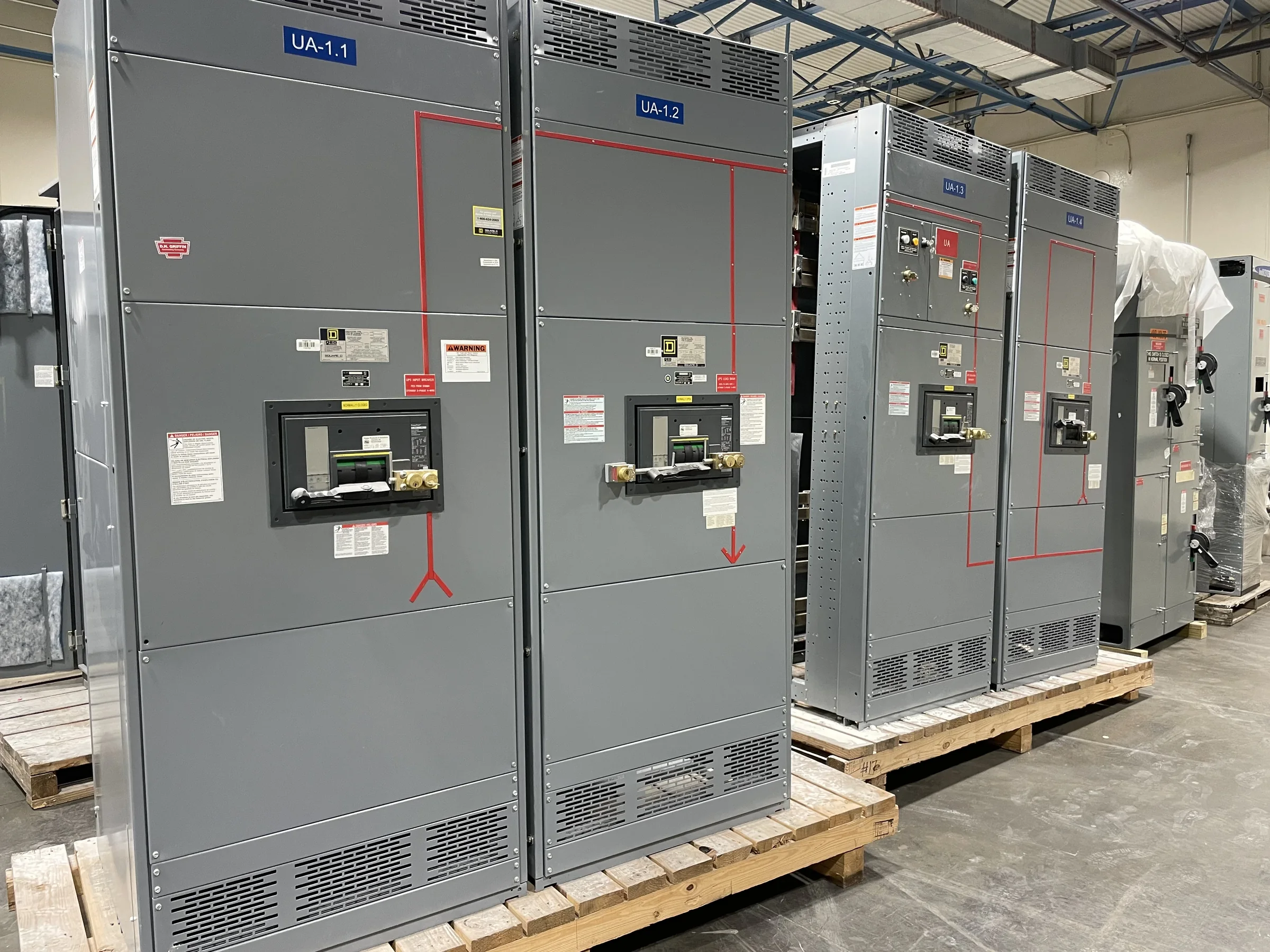
Define the 120/240V System Before Selecting Equipment
A 120/240V designation can describe different system arrangements, so begin with the source and load requirements rather than the voltage label alone. Confirm whether the project uses single-phase, three-wire service, and document the available conductors, grounding method, and utility or transformer source. This matters because panel or switchboard configuration, neutral treatment, and equipment compatibility depend on the actual system. List connected loads by voltage and phase, including motors, heating, lighting, receptacles, and any equipment with sensitive electronics. Identify present demand and planned additions; a distribution assembly sized only for today’s loads may leave no practical room for expansion. The manufacturer can review the project information and develop a new assembly around verified requirements, subject to engineering review.
Match the Assembly to Loads, Protection, and Expansion
Build the equipment schedule from the circuits the facility must serve, not from an assumed standard layout. Record each load’s voltage, phase, estimated demand, operating pattern, and required branch protection, then identify critical circuits that need a distinct distribution or coordination approach. For larger or mixed-use installations, an engineer should verify load calculations, conductor sizing, fault-current assumptions, and protective-device coordination against applicable codes and site conditions. Available fault current is especially important: protective equipment must have ratings suitable for the installation, and those ratings cannot be inferred from nominal voltage. Also decide how much spare capacity and physical space to reserve. Leaving provision for likely additions can reduce disruptive rework, while unnecessary oversizing can affect footprint, cost, and procurement.


Specify Ratings, Enclosure, and Interface Details
A useful request for quotation identifies the required electrical ratings and the boundaries between the new assembly and existing or planned equipment. Provide system voltage and configuration, bus and main-device requirements, interrupting or withstand criteria as applicable, metering needs, and the intended connection method. Confirm these details with the project engineer; ratings and configurations are not interchangeable simply because two assemblies share a voltage class. Enclosure selection should reflect the actual installation environment, including indoor or outdoor placement, exposure to dust or moisture, available working space, and access for operation and maintenance. Document cable entry direction, conduit locations, mounting conditions, and any obstructions. These details matter because an electrically suitable design can still create costly field changes if its dimensions or connections do not fit the site.
Prepare Drawings and Scope for a Comparable Quote
Procurement teams can improve quote accuracy by issuing one coordinated package rather than relying on a short equipment description. Include the one-line diagram, load schedule, equipment schedule, site plan or room layout, applicable specifications, and known interface information for upstream and downstream devices. Mark requirements that are mandatory separately from preferences, and identify who will approve submittals and resolve design questions. If replacement work is involved, provide verified existing dimensions, connection details, and available photographs or drawings, while clearly noting any information that still needs field confirmation. The distinction matters: incomplete or conflicting documents can lead to assumptions about ratings, layout, or scope that affect price and schedule. Ask the manufacturer to identify exceptions and open technical items so the team can resolve them before release.
Coordinate Schedule, Submittals, and Site Readiness
Discuss timing early, using the project’s required approval, fabrication, shipping, and installation dates as planning inputs rather than assuming a guaranteed lead time. The schedule depends on final specifications, design review, component availability, approved drawings, and any project-specific evaluation requirements. Agree on submittal milestones and designate reviewers who can return consolidated comments; delayed approvals can affect downstream work even when the equipment scope is clear. Before shipment, verify that the electrical room or mounting area is ready, access routes can accommodate the assembly, and the receiving team can handle unloading and staging. Check door clearances, turning space, floor conditions, and any lifting constraints with the site team. Early coordination helps prevent equipment arriving before it can be safely received or installed.
Plan Delivery, Installation, and Verification
Nationwide shipping can support projects in different regions, but delivery planning still needs the site’s receiving hours, unloading method, staging limits, and carrier access instructions. Confirm the destination contact and whether the shipment can reach the final installation area or only a designated receiving point. The distinction matters where access is restricted or equipment must pass through doors, corridors, or elevation changes. Installation should follow approved project documents and be performed by qualified personnel under the applicable safety procedures; the assembly must be de-energized before work, and energization requires appropriate inspection and authorization. Retain final drawings, equipment records, and commissioning documentation with facility files. For appropriately evaluated low-voltage switchboard assemblies, UL 891 may be relevant; applicability and any labeling must be confirmed for the specific assembly.