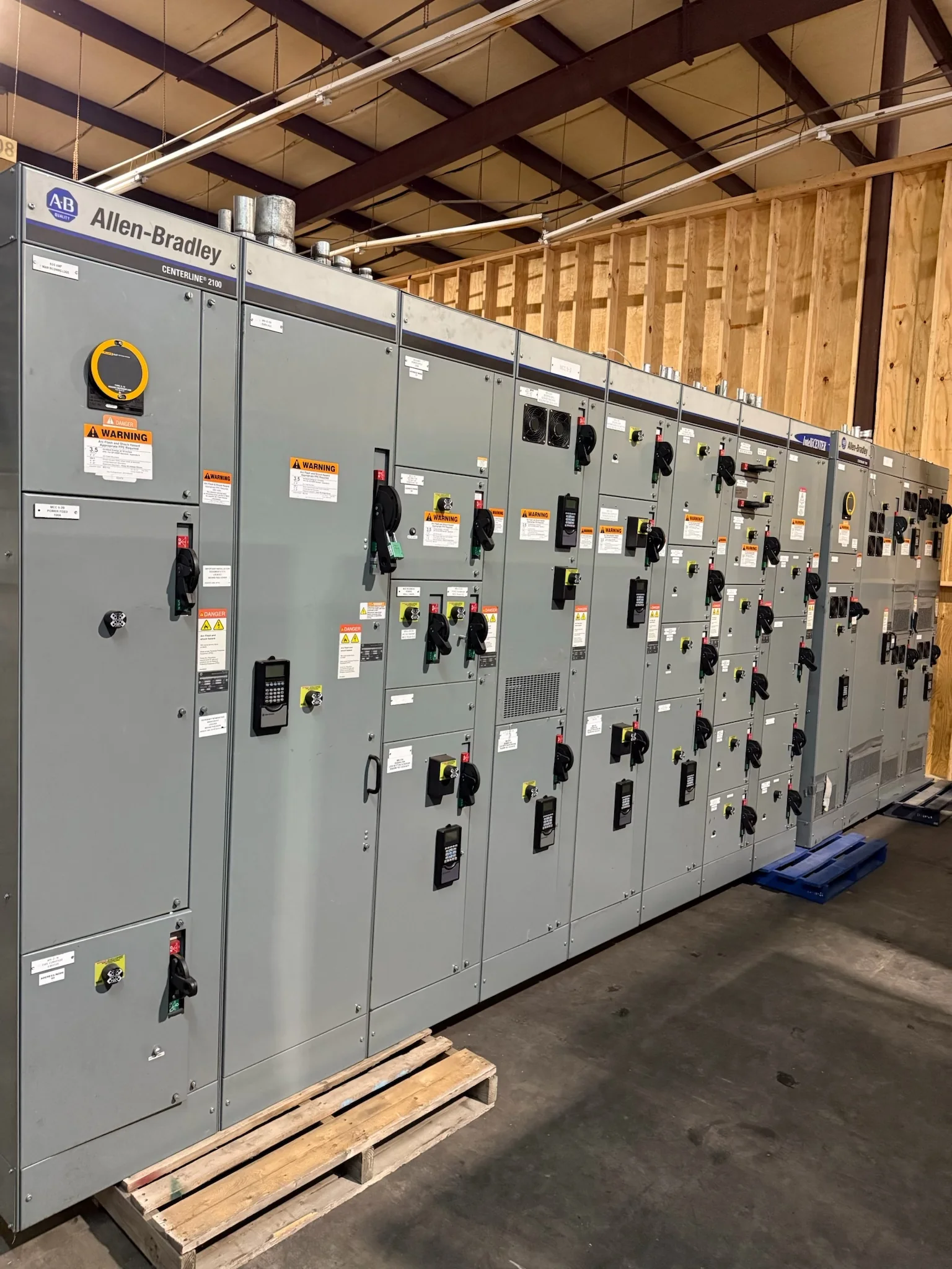
Define What “15 kV Class” Means for the Project
A 15 kV switchgear specification starts with the system’s actual operating voltage and insulation requirements—not just the label on an existing lineup. Confirm the nominal system voltage, maximum voltage, grounding method, fault-current study, and required withstand ratings with the engineer of record. These values affect equipment selection, protective-device coordination, and whether proposed gear can connect to the existing distribution system. Clarify whether the scope is metal-clad switchgear, metal-enclosed equipment, or another arrangement; the terms are not interchangeable. Also identify the service entrance, feeder count, bus configuration, and future expansion needs. A manufacturer can develop a new assembly around defined project criteria, but ratings, construction, applicable standards, and compatibility must be reviewed for the specific installation.
Build the Specification Around the Electrical Study
Protection and switching decisions should follow the project’s short-circuit, coordination, and arc-flash analyses rather than a generic catalog selection. Provide available fault current at the equipment terminals, upstream protective-device data, transformer information, and the intended relay or trip-unit functions. The reviewing engineer can use these inputs to evaluate interrupting and withstand requirements, settings, selectivity, and the consequences of adding new load. Specify metering, control power, instrument transformers, communications, and alarms only where the operating plan calls for them. This detail matters because a lineup that physically fits may still conflict with the protection scheme or plant controls. Identify approved relay families or interfaces when needed, while leaving final compatibility and settings subject to engineering review.


Coordinate Replacement Work With Existing Gear
For a replacement or extension, collect the existing switchgear drawings, nameplate data, one-line diagram, bus details, cable entry locations, and breaker or relay information before requesting a proposal. A 15 kV label alone does not establish that a new lineup will mate with old equipment or accept existing cables and control wiring. Document available room dimensions, aisle clearances, floor openings, overhead obstructions, and the route from the receiving point to the electrical room. Confirm whether the project needs a standalone lineup, a transition section, or a planned interface with existing gear. These checks expose fit and connection issues early, when the design can still address them, and help distinguish a workable replacement scope from an assumed drop-in substitution.
Plan Outage, Submittal, and Procurement Milestones
Procurement timing depends on the approved design, selected components, review cycles, and project-specific production and logistics; no calendar estimate should be treated as firm until the scope is reviewed. Start with a complete request package: operating voltage, one-line diagram, load and fault data, equipment arrangement, preferred protection and controls, site conditions, and required documentation. Identify who reviews drawings, how comments are resolved, and when approved-for-construction information is needed. For replacement work, align engineering and purchasing milestones with the planned outage window, since late changes can affect both construction readiness and shutdown planning. Ask the manufacturer to discuss current availability and schedule assumptions for the proposed configuration, and record those assumptions in the quotation and subsequent order documents.
Account for Installation Conditions and Delivery Access
A 15 kV lineup’s site fit is more than its footprint. Confirm room access, equipment handling path, door and ceiling clearances, floor capacity, environmental conditions, ventilation, cable trench or conduit locations, and the manufacturer’s installation requirements. Coordinate shipping sections and receiving arrangements with the construction manager, rigging contractor, and facility team; nationwide delivery does not remove the need to verify truck access, unloading equipment, staging space, or protection from weather. Establish who checks shipping condition, moves sections into position, makes field connections, and completes required inspections. These practical details matter because restricted access or an unprepared electrical room can delay installation even when the equipment design is complete. Site-specific plans should be resolved before shipment is scheduled.
Review Submittals, Testing, and Turnover Requirements
Before release, compare the proposed lineup and drawings against the project specification, one-line diagram, equipment schedule, and interface requirements. Resolve exceptions for ratings, dimensions, protection, metering, control circuits, communications, and included accessories in writing. Request the project’s applicable documentation, such as arrangement and connection drawings, component data, operating instructions, and test records where required by the contract. Define inspection and acceptance responsibilities, along with the sequence for installation, commissioning, and energization; electrical work must be performed under qualified supervision and with required de-energization and safety controls. UL 891 applies to appropriately evaluated low-voltage switchboard assemblies, not as a blanket designation for 15 kV equipment. Confirm the relevant standards and any evaluation or labeling requirements for the specific assembly before procurement.