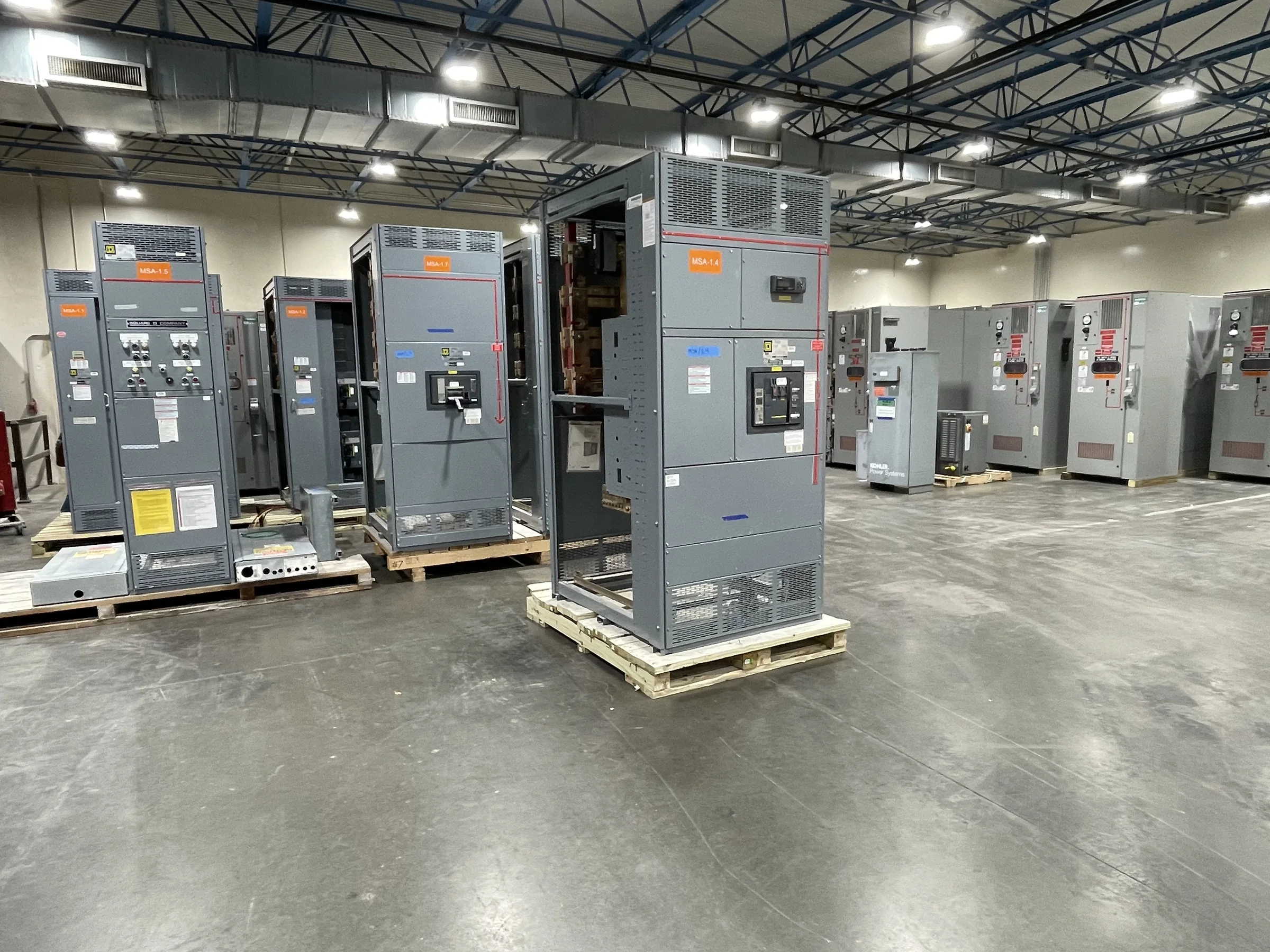
Define the Replacement Boundary Before Selecting Equipment
In Baytown, a switchgear replacement may affect a single lineup, a service entrance, or several connected distribution sections serving process, utility, and support loads. Establish the boundary by tracing the one-line diagram against field conditions: identify incoming sources, tie breakers, downstream feeders, protective devices, and any equipment that will remain. This matters because a new assembly must connect safely and functionally with retained gear, not just fit the available floor space. Record existing nameplate data, bus arrangement, enclosure dimensions, cable or busway entry points, and control interfaces where accessible. Have qualified personnel verify conditions using the facility’s safety procedures. If drawings are outdated or equipment labels are unclear, make those uncertainties explicit in the request for quote so engineering review can address them before design is finalized.
Specify Electrical Ratings and Protection Around the Actual System
Replacement specifications should describe the electrical system the new equipment must serve, rather than relying only on the old switchgear’s nameplate. Provide system voltage, frequency, phase, available fault-current information, grounding method, source configuration, and the intended continuous load. The engineer of record must evaluate interrupting or short-circuit ratings, bus ratings, and protective-device coordination against the installation and applicable requirements. In Baytown industrial facilities, operating changes, added process loads, or utility-source modifications may mean historical settings and fault studies no longer reflect present conditions. Submit existing studies and relay or trip-unit data for review, but do not assume they remain suitable. The final equipment configuration, ratings, and standards applicability are project-specific; confirming them early helps avoid a technically incompatible quote or redesign after procurement begins.


Resolve Interfaces With Retained Equipment and Controls
A replacement lineup often has to work alongside equipment that is not being replaced. Document connection details for adjacent switchgear, transformers, generators, transfer equipment, motor-control centers, and building or process control systems. Note whether feeder conductors enter from above or below, whether existing bus connections can be reused, and what metering, alarms, interlocks, or communications the facility requires. These details matter because an electrical match alone does not ensure mechanical fit or correct system operation. Provide control schematics, terminal schedules, and relevant device information when available, and identify any planned changes to the operating sequence. Do not assume an older protective device, communications protocol, or interlock will integrate with new equipment without engineering review. Confirm interface responsibilities among the manufacturer, contractor, and facility team before releasing approved drawings.
Plan the Baytown Site Work and Delivery Route
Baytown projects may involve active industrial sites, controlled gates, contractor check-in, designated unloading zones, and restricted access near operating process areas. Confirm site-specific requirements before scheduling shipment: delivery hours, advance notice, driver credentials, escort rules, truck dimensions, dock or crane availability, and the route from the receiving point to the electrical room. The lineup’s shipping sections and handling provisions must also suit door openings, corridors, overhead obstructions, floor capacity, and the final placement path. These checks matter because a truck can reach the facility while the equipment still cannot reach its installation location. Share verified access dimensions and site constraints during quotation and drawing review. Nationwide shipping and custom construction can support project planning, but shipping method, packaging, sectional arrangement, and delivery timing must be confirmed for the specific order.
Coordinate Outage, Removal, and Commissioning Responsibilities
The equipment purchase is only one part of a successful replacement. Develop an outage plan with facility operations and the electrical contractor that identifies affected loads, temporary power needs, removal scope, installation sequence, inspection points, and the party responsible for each task. This is especially important where a process interruption could affect production or environmental controls. Set expectations for submittal review, fabrication release, site readiness, incoming inspection, and commissioning well before the planned outage; do not treat a quoted schedule as a guaranteed delivery date. All work on existing electrical equipment must follow applicable safety procedures, including required de-energization, lockout/tagout, verification, and qualified-person practices. Define who will perform testing and startup, what acceptance records are required, and how discovered field differences will be handled before crews mobilize.
Prepare a Complete RFQ and Closeout Record
A useful request for quote gives the manufacturer enough information to evaluate the application without guessing. Include the one-line diagram, equipment schedule, available fault-current or coordination information, photographs, dimensional measurements, cable or busway details, required accessories, and the intended scope of replacement. State whether the project calls for new low-voltage switchboard assemblies, other switchgear, or a combination; UL 891 applies only to appropriately evaluated low-voltage switchboard assemblies and is not a blanket certification for medium- or high-voltage equipment. Ask for project-specific submittals, deviations, and clarification of standards and labeling requirements rather than presuming them. After approval, retain the final drawings, device data, settings documentation, test records, and operating instructions with facility records. A complete closeout package supports future maintenance and makes later system changes easier to evaluate.