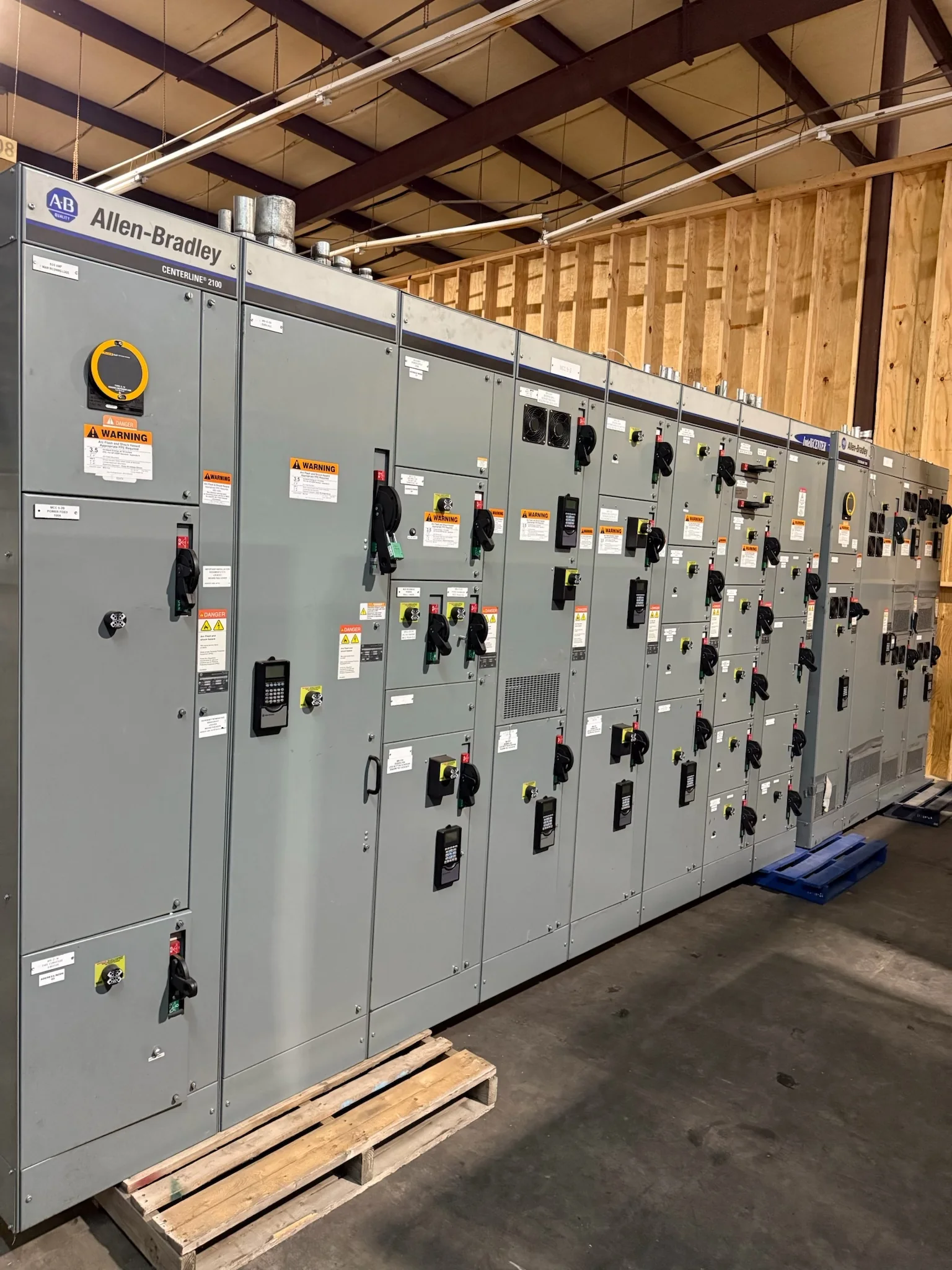
Define What 2,500 Amps Means for the Project
A 2,500-amp designation is a starting point for equipment selection, not a complete design specification. Confirm whether the requirement applies to a switchboard, switchgear lineup, main bus, or a particular section, and identify the system voltage, phase, frequency, and grounding arrangement. The available fault current and required interrupting or withstand ratings must also be established from the project’s electrical study; the ampere rating alone does not determine them. Clarify whether the equipment is service entrance, downstream distribution, or part of a generator or utility transition. These distinctions affect configuration, protection, and documentation. A manufacturer can develop a new assembly around confirmed project requirements, but final ratings and compatibility depend on the design and applicable evaluation.
Coordinate Protection, Loads, and Future Capacity
At this current level, the main device and downstream distribution need to be considered as one coordinated system. Provide a current one-line diagram, transformer data, available fault-current information, protective-device requirements, and a load schedule that separates continuous, intermittent, and planned loads. Engineers can use these inputs to review feeder arrangement, breaker or switch-device selection, and coordination with upstream and downstream protection. Avoid treating spare spaces as a substitute for verified future capacity: bus capacity, enclosure space, heat dissipation, and protection settings may each constrain later expansion. If loads include large motors, variable-frequency drives, or nonlinear equipment, identify them early because starting behavior and harmonics may influence system studies and equipment decisions. Final settings and application suitability are project-specific.


Choose a Configuration That Fits the Electrical Room
A 2,500-amp assembly can create substantial demands on room layout and installation access, so check the actual equipment outline against the building before release. Compare lineup length, depth, height, cable-entry direction, working space, doors, structural supports, and the path from the receiving point to the final location. Cable bending and termination space can be decisive, particularly where large conductors enter from below or above. Confirm whether the design must interface with existing switchboards, switchgear, transformers, generators, or busway; connection dimensions and electrical characteristics need documented review rather than assumption. Include environmental conditions such as indoor or outdoor placement, temperature, dust, moisture, and corrosive exposure. These practical checks help prevent late layout changes, access conflicts, and costly field modifications.
Prepare Submittals and Interface Information Early
Complete project documentation makes review more useful and reduces avoidable clarification cycles. A procurement package should identify the required equipment type, system data, main and feeder functions, metering needs, control circuits, enclosure conditions, cable arrangements, and any specified standards or owner requirements. Include one-line and plan drawings, equipment schedules, short-circuit and coordination-study criteria, and relevant interface drawings where available. For replacement work, provide existing nameplates, dimensions, connection details, and photographs, while recognizing that field verification is still important. The manufacturer’s proposed submittals should be checked against the approved design before fabrication; changes after approval can affect layout, interfaces, cost, and schedule. UL 891 applies to appropriately evaluated low-voltage switchboard assemblies, not universally to every 2,500-amp product.
Plan Schedule Around Design Approval and Site Readiness
Discuss timing at the beginning of procurement, but base the project schedule on the confirmed configuration, review process, and current component availability rather than an assumed standard lead time. Custom details, protection requirements, metering, special enclosures, and unresolved interfaces can affect engineering and production planning. Establish who reviews drawings, how comments are consolidated, and when approved-for-production documentation is needed. In parallel, confirm the room is ready for receiving and installation: foundations or housekeeping pads, access openings, lifting provisions, clearances, and grounding connections should align with the approved drawings. Coordinate required outages and commissioning activities with the facility team. Installation, inspection, testing, and energization must follow project procedures and qualified personnel requirements; equipment should not be treated as ready to energize merely because it has arrived.
Coordinate Delivery, Receiving, and Replacement Scope
Nationwide shipping can support projects in different regions, but delivery planning still depends on the site, carrier access, and equipment configuration. Confirm the receiving address, delivery window, unloading responsibility, dock or lift requirements, route restrictions, storage conditions, and who will inspect the shipment on arrival. A large assembly may need staged delivery or coordinated handling; verify those details against the final shipping dimensions and site plan rather than relying on general assumptions. For replacement or retrofit work, define whether the scope includes only new equipment or also engineering interfaces, field measurements, installation, and commissioning. Document existing system conditions and any required outage window before ordering. A U.S. manufacturer can discuss a new 2,500-amp build, American-component preferences, and project-specific delivery coordination; availability and timing require confirmation.