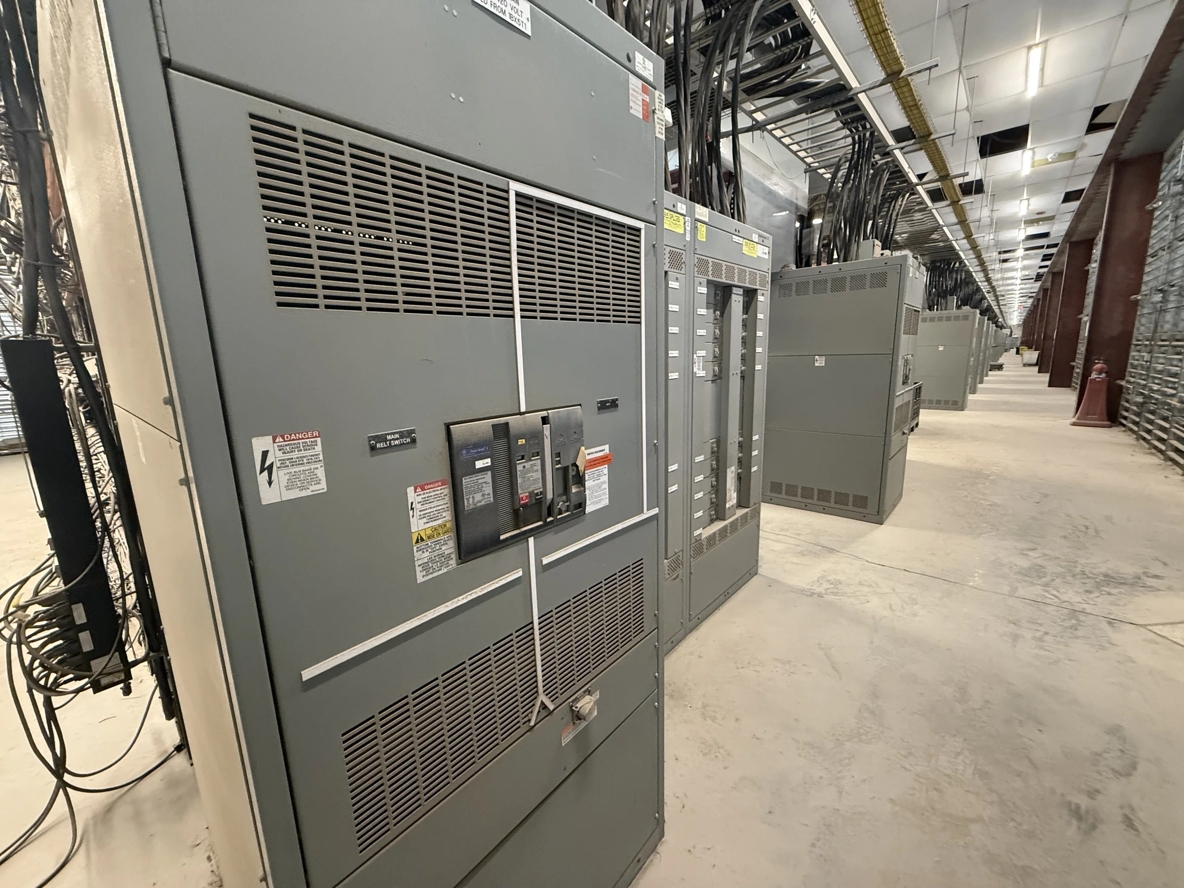
Define What 3,000 Amps Means for the Assembly
A 3,000-amp designation describes a current rating, not a complete equipment specification. Before requesting a quote, identify whether the project calls for a low-voltage switchboard, switchgear, or another distribution arrangement, and document the system voltage, phase, frequency, and intended service. The assembly’s bus rating, protective-device ratings, available fault current, and operating conditions must be evaluated together; choosing equipment by amperage alone can leave important coordination or application questions unresolved. Clarify whether 3,000 amps applies to the main device, the bus, or another part of the proposed lineup. Share one-line diagrams and load information early so the manufacturer can review the intended configuration. Final ratings and suitability depend on project conditions, applicable standards, and equipment evaluation.
Match the Main Device and Protection to the System
The main protective device affects how a 3,000-amp lineup connects to the source and responds to faults, but its selection depends on more than the nominal current. Engineers should provide the available short-circuit current at the equipment, upstream protective-device information, grounding arrangement, and any required coordination or arc-flash study criteria. These details help establish whether the proposed device and assembly are suitable for the electrical system and how downstream feeders should be arranged. A 3,000-amp rating does not by itself establish interrupting capacity, withstand capability, or a particular protection scheme. Confirm these values against the project study and governing requirements rather than assuming them from the amperage. If study inputs or utility data are still pending, identify that early so design review can account for open decisions.


Plan the Lineup Around Loads and Future Changes
A useful 3,000-amp design starts with a feeder schedule, not an assumed row of standard sections. List connected loads, feeder quantities, protective-device types, cable or bus connections, and any spare or future positions the facility expects to use. Large motor loads, process equipment, HVAC systems, and distributed generation can affect how the lineup is configured and how protection is coordinated; their operating characteristics should be represented in the project documents. Also identify whether the equipment must support metering, communications, maintenance access, or separation of particular functions. These choices influence compartment layout and cable space, so leaving them until fabrication drawings can trigger avoidable revisions. Future capacity should be described as a defined design objective, not treated as guaranteed merely because the bus carries a 3,000-amp rating.
Check Room Access, Clearances, and Cable Entry
A lineup that fits an electrical room on paper may still be difficult to install or maintain. Before approving a proposed 3,000-amp assembly, verify room dimensions, door and corridor widths, turning space, floor and housekeeping-pad conditions, overhead obstructions, and the route from unloading point to final position. Identify cable-entry direction, conduit locations, bending space, and whether connections approach from above, below, or another arrangement. Required working space and access must be checked against applicable codes and the actual equipment configuration; do not assume a compact layout can override them. Construction teams should also confirm rigging and handling constraints, since section size and weight are project-specific. Sharing a dimensioned room plan and delivery-path details before release can prevent costly field changes and installation delays.
Prepare the Submittal Package Before Release
Clear project documents help procurement, engineering, and the manufacturer resolve questions while changes are still manageable. A quote request should identify the service conditions, requested 3,000-amp application, quantity, target project milestones, shipping destination, and known standards or owner requirements. Include the latest one-line diagram, load and feeder schedules, fault-current or coordination data when available, room plan, and connection details. Ask reviewers to verify device functions, metering, cable space, dimensions, and interfaces with existing equipment against the contract documents. For low-voltage switchboard assemblies, UL 891 may be relevant when applicable to the evaluated assembly and project requirements; it is not a blanket certification for all switchgear or voltage classes. Confirm required labeling, documentation, and acceptance criteria for the specific equipment rather than assuming applicability.
Coordinate Build Timing and Delivery to Site Readiness
Discuss schedule and shipping early, using the project’s required dates as planning inputs rather than treating a lead-time estimate as a guarantee. Custom configurations, drawing review, component availability, approvals, and changes to the feeder or protection scheme can all affect a release schedule. Ask the U.S. manufacturer to identify information needed to complete design review and clarify when the delivery window can be assessed for the selected build. Nationwide shipping is available, but delivery coordination still depends on the destination, unloading arrangements, access restrictions, and site readiness. Confirm who receives the shipment, where equipment can be staged, and whether the route and lifting plan have been reviewed. Align delivery with the electrical room’s completion and installation resources; equipment arriving before the site is ready can create storage, handling, and damage risks.