Define What 3,200 Amps Means for the Project
A 3,200-amp designation identifies a current rating, not a complete equipment specification. Before requesting a quote, establish whether the project calls for a low-voltage switchboard or switchgear, and document the system voltage, phase, frequency, available fault current, main-device arrangement, and required distribution devices. The equipment’s continuous-current rating must suit the application, while its short-circuit and interrupting capabilities must be evaluated against the available fault current and system design. Also clarify whether the stated 3,200 amps applies to the main bus, service equipment, or another defined portion of the assembly. These distinctions affect equipment selection, protective-device coordination, utility review, and physical layout. Confirming them early prevents an amp-rating label from obscuring requirements that determine whether the proposed assembly is suitable.
Choose the Assembly Around Loads and Protection
A large service rating does not, by itself, determine how loads should be grouped or protected. Provide a current load schedule that distinguishes existing loads from planned additions, identifies major motors and other significant equipment, and notes expected operating patterns where known. Engineers can use this information, along with applicable demand calculations and project criteria, to develop a distribution arrangement and evaluate feeder and overcurrent-device requirements. Identify critical loads, standby or emergency sources, metering needs, and any required separation or selective coordination criteria. These choices influence the number and arrangement of sections, device types, and connection points. If the building will expand in phases, describe the intended sequence and reserve requirements rather than assuming unused spaces or future capacity can be added without design review. Final ratings and configuration remain project-specific.


Resolve Fault Current, Coordination, and System Interfaces
Available fault current at the equipment location is a key input, not a value to estimate from the 3,200-amp rating. Obtain the utility’s applicable data and upstream transformer and conductor information, then have the project’s qualified electrical professionals evaluate the system and protective-device coordination. Confirm how the equipment interfaces with upstream protection, downstream distribution, grounding, metering, and any generator or other alternate source. Changes to transformer size, feeder length, or system configuration can change fault-current conditions and affect equipment requirements. Document the assumptions used for the evaluation and identify who is responsible for confirming them before release for manufacture. Do not treat a proposed interrupting or withstand value as confirmed until the applicable design and equipment evaluation support it. Exact ratings, device selections, and standards depend on the project.
Check Room Layout, Access, and Installation Conditions
A 3,200-amp assembly can impose substantial demands on the electrical room, so verify usable space before approving a lineup. Provide dimensioned room plans showing doors, columns, structural obstructions, cable trenches, adjacent equipment, and required working clearances. Confirm the proposed equipment’s access and service requirements with the design team, including how personnel will reach operating handles and removable or serviceable components. Cable entry direction, conductor bending space, busway connections, and the location of incoming and outgoing feeders can affect both lineup dimensions and field installation. Check floor loading, anchorage, and the route from the receiving point to the final room; narrow doors, elevators, turns, or limited staging areas may constrain handling. Resolve these conditions during design review, because a physically incompatible assembly can delay installation even when its electrical ratings are appropriate.
Prepare Submittals That Support Review and Release
A useful quote package gives the manufacturer enough information to identify open engineering decisions without disguising them as settled requirements. Include one-line diagrams, equipment schedules, load and feeder information, utility fault-current data, room and cable-entry drawings, applicable project specifications, and the requested delivery destination. State the governing standards and any project-specific inspection, labeling, metering, or documentation requirements. If the scope includes replacement or retrofit work, provide verified existing-equipment information, photographs, interface dimensions, connection details, and the planned outage window; field conditions should be checked before finalizing compatibility. Ask for proposed drawings and submittals that let the engineer of record review ratings, arrangement, and interfaces before production release. Clarify document review responsibilities and the effect of revisions. UL 891 applies to appropriately evaluated low-voltage switchboard assemblies; it is not a blanket certification for all switchgear.
Plan Schedule and Delivery Around Site Readiness
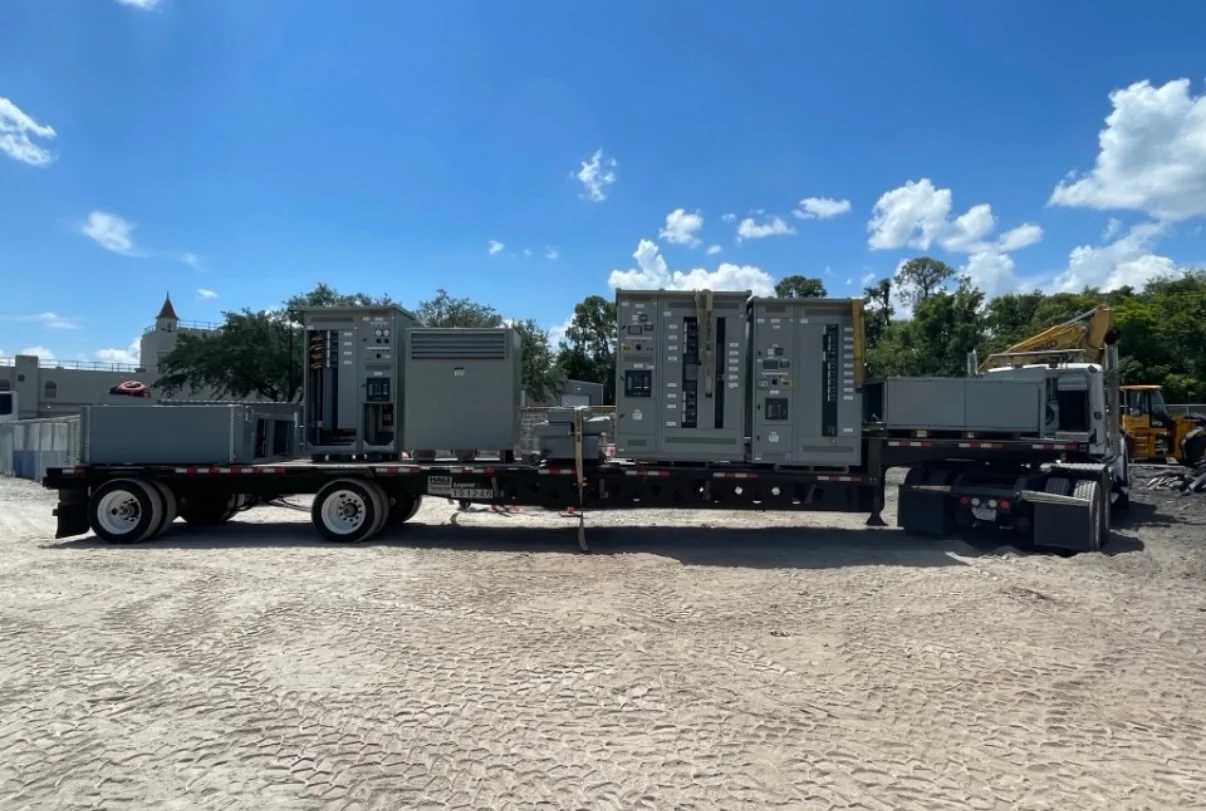
Discuss schedule assumptions with the U.S. manufacturer when defining scope, because design approval, component selection, drawing review, and project changes all influence production timing. Short lead times may be available, but a delivery period should not be assumed until requirements, configuration, and availability are reviewed for the specific order. Confirm the shipping destination, receiving hours, unloading equipment, site contact, and whether the truck can reach the building or only a designated dock. Coordinate delivery with room readiness, access control, rigging, contractors, and any planned outage or construction sequence. For facilities with restricted access, occupied operations, or limited staging, determine where the assembly will be received and protected before installation. Identify the party responsible for checking shipment condition and resolving transit or receiving issues. Nationwide shipping is offered; routing, handling, timing, and site coordination remain project-specific.