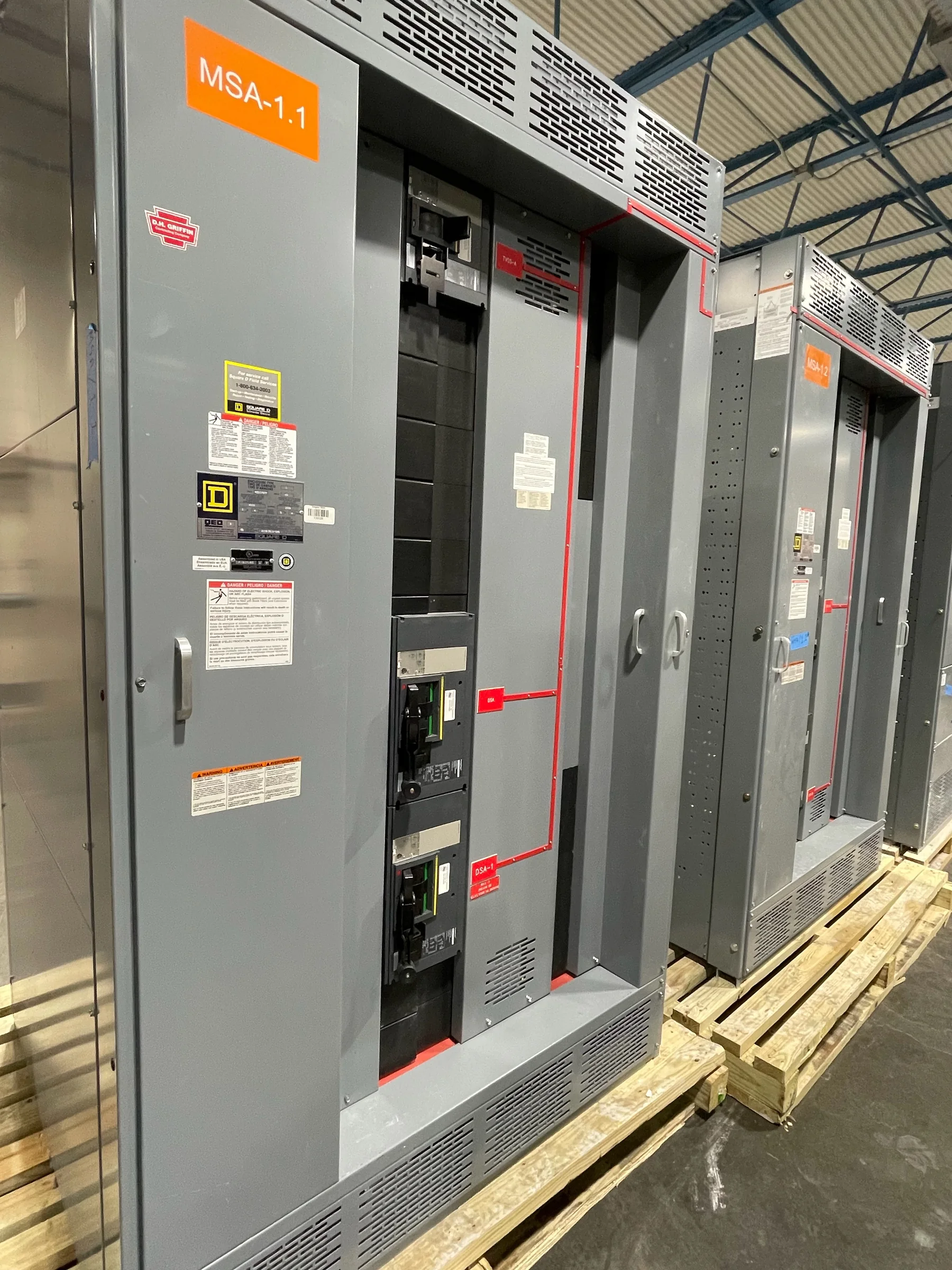
Confirm What “347/600V” Means for the Project
A 347/600V designation usually refers to a three-phase, four-wire system with 600 volts between phases and 347 volts from phase to neutral. Confirm that this is the actual service voltage and grounding arrangement before selecting switchgear; a nominal voltage label alone does not establish compatibility. Review the utility information, one-line diagram, transformer data, and existing equipment nameplates, and resolve discrepancies before requesting a build. The design also needs to account for the system’s available fault current, required interrupting ratings, and protective-device coordination. These values are site- and configuration-specific, not assumptions to carry over from a similar facility. A U.S. manufacturer can develop new distribution equipment around documented project requirements, with final ratings and construction confirmed through engineering review.
Define the Distribution Duty Before Comparing Proposals
Start the equipment schedule with the electrical duty of each feeder and incoming section, not just the total connected load. Identify continuous loads, motor starting characteristics, transformers, large rectifiers, and other equipment that may affect demand or fault behavior. Document the required bus arrangement, incoming source configuration, feeder count, spare capacity, metering, and any provisions for future expansion. In a 347/600V system, 347V line-to-neutral circuits may serve lighting while 600V circuits supply larger loads, so the neutral and feeder requirements deserve explicit review. A clear scope helps procurement compare equivalent proposals and helps engineering catch omissions before fabrication. Final bus ratings, protective-device selections, and available features depend on the application and verified design inputs.


Coordinate Protection, Interfaces, and Existing Equipment
Replacement or expansion work must fit the electrical system it joins, not merely the space occupied by the old lineup. Gather existing one-lines, control schematics, breaker information, cable schedules, and equipment dimensions; record bus connections and the location of incoming and outgoing conductors. The engineer should evaluate short-circuit duty and protective-device coordination across connected sources and loads. Where generators, transformers, or parallel sources are involved, their operating modes can change fault levels and protection requirements. Also identify signals, interlocks, metering communications, and control-power interfaces that must remain compatible with adjacent equipment. These details affect design, review, and commissioning planning. Do not assume a new assembly can reuse existing breakers or connect directly to an existing bus without confirming compatibility and documenting the engineering basis.
Plan the Footprint, Access, and Installation Sequence
A lineup that meets electrical requirements can still create a difficult installation if access and handling are considered too late. Verify the room dimensions, clearances required by the applicable design, door swings, cable entry paths, floor conditions, and the route from the receiving point to the final location. Check doorway heights, turns, elevators, loading limits, and whether the equipment must be handled in sections. For a replacement, plan how existing conductors will be identified and how outages, temporary arrangements, removal, and installation will be coordinated by qualified personnel. Site conditions and approved drawings determine what is practical. Early review gives the manufacturer a chance to address enclosure layout and shipping configuration in the project scope, while helping the facility team anticipate rigging, access, and work sequencing constraints.
Make Submittals and Purchasing Requirements Actionable
A useful request for quotation includes the one-line diagram, load and feeder schedules, service characteristics, fault-current information, enclosure requirements, and any owner or consultant specifications. State the required standards and acceptance criteria rather than relying on a generic description of “switchgear.” UL 891 applies to appropriately evaluated low-voltage switchboard assemblies; it is not a blanket certification for every 347/600V product or for medium- and high-voltage equipment. Confirm the requested equipment classification and labeling with the project engineer and manufacturer. Submittals should give reviewers enough information to check ratings, dimensions, bus configuration, protective devices, metering, and interfaces before release to production. A complete, consistent package reduces clarification cycles and supports a more realistic purchasing decision; final compliance and availability remain specific to the approved design.
Discuss Timing and Delivery Before the Site Is Ready
New equipment timing depends on the approved scope, design review, component availability, release of submittals, and any requested changes; do not treat a preliminary estimate as a guaranteed ship date. Ask the manufacturer to identify the assumptions behind its schedule and explain when required customer approvals or information affect progress. U.S. manufacturing, American components, custom builds, short lead times, and nationwide shipping are offerings to discuss for the project, not substitutes for confirming a specific configuration and delivery plan. Coordinate the shipping destination, receiving hours, unloading equipment, storage conditions, and who will inspect and document the shipment. If construction or outage dates are fixed, share them early and maintain contingency in the site plan. Delivery coordination matters because a completed lineup still needs safe access, proper handling, and a ready installation area.