Define What “35 kV” Means for the Project
A 35 kV designation is a starting point for equipment selection, not a complete switchgear specification. Confirm the system’s nominal voltage and maximum operating voltage, grounding method, frequency, insulation requirements, and the available fault current at the proposed connection. Those values affect the equipment class, interrupting and withstand requirements, bus design, and protective-device coordination. Clarify whether the scope is metal-clad switchgear, a switching arrangement, or other distribution equipment; the terms are not interchangeable. Also establish whether the utility or an engineer of record has issued governing requirements. Providing a one-line diagram and available short-circuit study early helps the manufacturer identify missing inputs before a quotation is treated as a design basis.
Match the Configuration to the Distribution Scheme
The 35 kV lineup should reflect how power is received, sectionalized, protected, and distributed—not simply the number of feeder positions on an early sketch. Review incoming sources, bus sections, tie arrangements, transformer connections, metering, and the operating sequence for normal and contingency conditions. If the facility depends on alternate feeds, define how transfer is controlled and what interlocking is required; an assumed operating sequence can create unsafe or unusable arrangements. Identify each load and its protection needs, including motor starting or transformer inrush where relevant. A current one-line diagram, load list, and control narrative allow the design team to check that the proposed lineup supports the intended distribution plan and leaves practical room for future changes.


Specify Ratings, Protection, and Interfaces Together
Voltage class alone does not establish whether equipment is suitable for a particular point on the system. The project team should document continuous-current needs, fault duty, insulation level, environmental conditions, and applicable utility or owner criteria, then confirm the required ratings against the system study. Protection details matter just as much: relay functions, instrument-transformer requirements, trip and close control power, communications, and coordination with upstream and downstream devices must be defined. Identify interface boundaries with transformers, cables, grounding, and building systems, including who supplies terminations and control wiring. These items influence compartment arrangement and factory scope. Because requirements and compliance obligations are project-specific, drawings and approved submittals should establish the final basis before manufacture.
Plan the Room, Cable Routes, and Installation
A workable electrical room needs more than a footprint on an architectural plan. Check lineup dimensions and access clearances against doors, corridors, structural openings, overhead obstructions, floor loading, and the route from the unloading point to the final position. For 35 kV equipment, cable approach, termination space, bending room, and grounding provisions deserve early coordination with the electrical contractor and equipment designer. Confirm whether conductors enter from above or below and whether trenches, pull spaces, or removable panels are part of the design. Review ventilation, ambient conditions, moisture exposure, and contamination risks for the actual site. Resolving these constraints before release helps avoid field modifications, blocked access, and cable installation problems.
Coordinate Procurement, Submittals, and Delivery
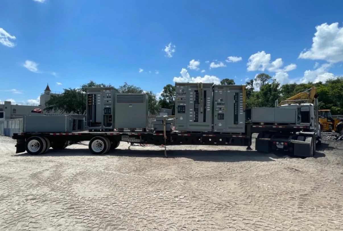
A purchase schedule should account for engineering review and site readiness, not just the date equipment is needed. Submit complete requirements with the request for quotation: one-line diagrams, specifications, site conditions, control requirements, preferred scope boundaries, and requested documentation. Ask the U.S. manufacturer to identify assumptions, exclusions, and information still needed, and discuss current production timing rather than relying on an unverified allowance. Confirm shipping destination, receiving hours, unloading responsibility, storage conditions, and whether the delivery can be accepted in the planned sequence. Long-distance shipment may require coordination among the carrier, site team, and installer, especially where access or lifting capacity is limited. Timing and availability remain specific to the approved configuration and order.
Prepare for Review, Testing, and Energization
Before release, compare the approved equipment drawings with the one-line diagram, protection study, cable schedule, and control interfaces; discrepancies are easier to resolve on paper than at installation. Define the project documents required at handoff, such as final drawings, wiring information, operating instructions, and applicable test documentation, and agree on review responsibilities. Establish who will receive, inspect, store, install, and commission the equipment, including how damage or missing components will be recorded. Installation, inspection, testing, and energization must follow the manufacturer’s instructions, approved project documents, and applicable codes, with electrical work performed under qualified supervision and equipment de-energized as required for the task. Confirm the site’s commissioning plan and acceptance criteria before shipment so the team can prepare the room and personnel.