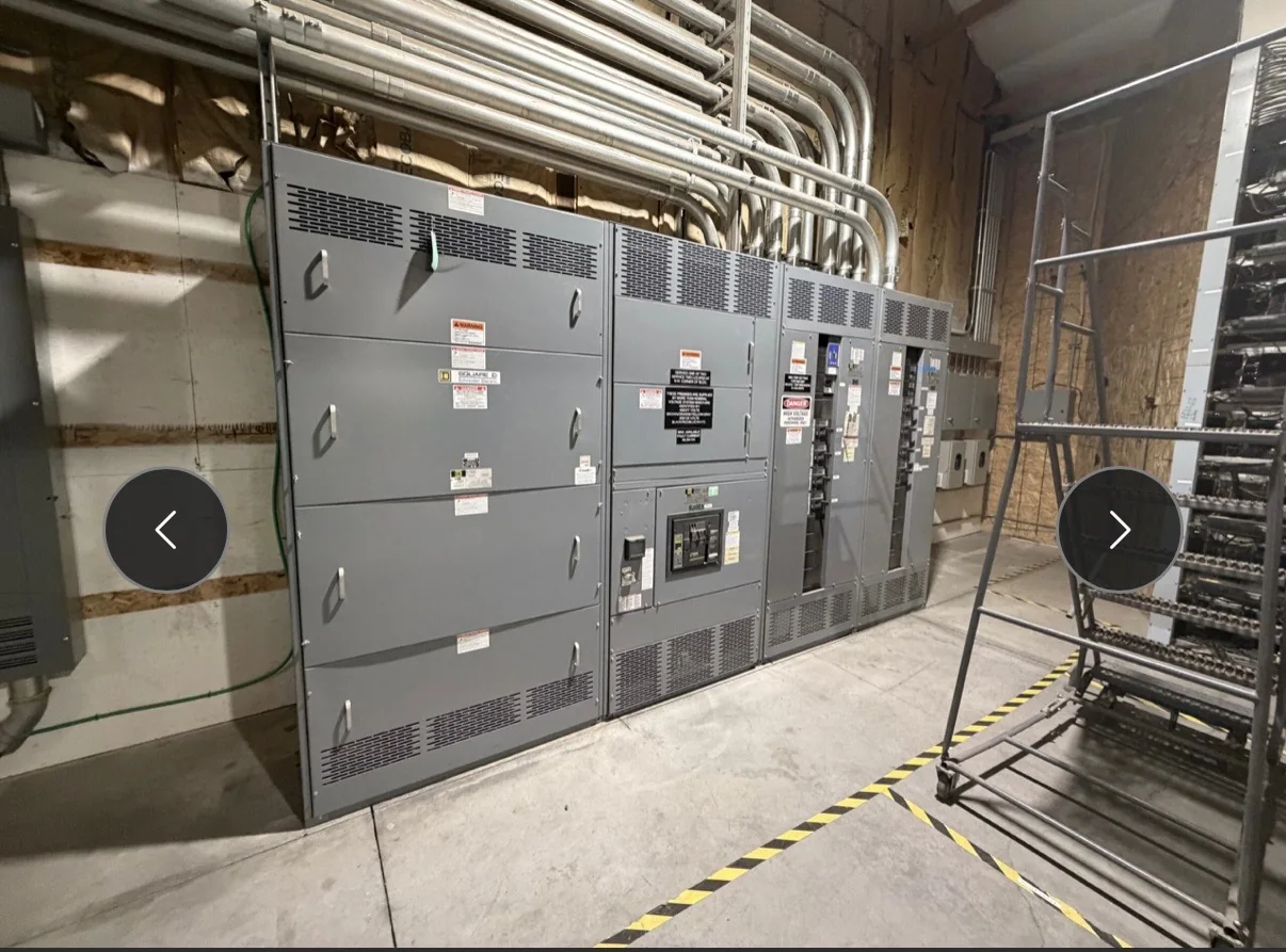
Define What 5 kV Means for the Installation
A 5 kV system is a nominal voltage class, not a complete equipment specification. Before requesting a quote, identify the system voltage, grounding method, available fault current, frequency, and the intended source and load connections. Confirm whether the project needs metal-enclosed switchgear, a switchboard, or another distribution arrangement; these terms describe different equipment and should not be treated as interchangeable. The one-line diagram should show incoming sources, bus ties, transformers, feeders, metering, and protective devices. These details matter because an assembly must be evaluated for its actual duty and configuration, not selected by voltage alone. Provide existing equipment data where the project involves replacement, and flag any known constraints or unresolved values for engineering review.
Coordinate Protection, Switching, and System Interfaces
Protection and switching choices depend on the power system, connected loads, and operating sequence. Share available short-circuit and coordination studies, relay requirements, instrument-transformer needs, and any arc-flash study criteria when available. Identify whether the lineup must interface with utility equipment, generators, transformers, motors, or a plant control system; interface details can affect compartment arrangement, wiring, and commissioning plans. Do not assume existing protective settings or device families will transfer directly to new equipment. A change in breaker, relay, or transformer characteristics may alter coordination and fault-clearing performance. The manufacturer and project engineer should resolve those interfaces against the approved design. Clear responsibility for studies, settings, field wiring, and final acceptance helps prevent scope gaps late in procurement.


Check the Room, Access Route, and Operating Space
A technically suitable lineup can still create installation problems if the room and delivery path are not checked early. Supply room dimensions, ceiling height, door and corridor clearances, floor conditions, conduit entry locations, and the planned equipment orientation. Note restrictions such as narrow turns, loading-dock limits, stairs, or overhead obstructions, and confirm who will coordinate unloading and movement into the electrical room. Required working clearances, access for maintenance, ventilation, and cable bending space must be reviewed against the applicable design and installation requirements; they should not be inferred from a catalog image. These checks matter because equipment sections may arrive as coordinated assemblies with specific handling needs. Early review helps align lineup dimensions, shipment breakdown, rigging plans, and construction sequencing.
Plan Replacement Work Around Outage and Cutover Needs
For a replacement project, document the existing lineup’s manufacturer, model, nameplate information, dimensions, bus arrangement, cable connections, and known operating issues. Photographs and marked-up drawings can help identify conditions that are absent from old records, but they do not replace field verification by qualified personnel. Establish the required outage window, temporary-power strategy, demolition boundaries, and cutover responsibilities with the facility team. This planning matters because a new 5 kV assembly may not match the old footprint, terminations, or protection scheme, even when it serves the same loads. Confirm which existing cables and controls are candidates for reuse and which require new work. All inspection, connection, testing, and commissioning activities must follow the approved safety procedures and occur with equipment properly de-energized where required.
Submit a Complete RFQ Package and Review Documents
A useful request for quotation includes the one-line diagram, equipment schedule, applicable project specifications, site and environmental conditions, and requested options or accessories. Identify the required standards and any owner-specific requirements, but have applicability confirmed for the proposed equipment and project. Ask which drawings and submittals are included, what information is needed for approval, and how revisions will be handled. Review the bill of material, ratings, device descriptions, control and metering points, dimensions, and connection details before releasing the equipment for manufacture. This step matters because ambiguous scope can lead to mismatched interfaces or delayed approvals. Record exceptions and open questions in a written clarification log. Final ratings, construction, compliance, and availability remain subject to project-specific engineering review and confirmation.
Discuss Build Timing, Shipping, and Site Readiness
Build timing depends on the confirmed design, component availability, drawing approvals, and the scope of the assembly; request a project-specific schedule rather than relying on a general lead-time statement. The U.S. manufacturer offers custom builds, American components, short lead times, and nationwide shipping, with exact configuration and availability confirmed for each project. Coordinate the requested ship date with site readiness, receiving hours, storage conditions, unloading equipment, and installation sequencing. Ask how the shipment will be divided, what handling information accompanies it, and which documents are supplied for receiving and installation. These details matter when a site has limited staging space or a planned outage that cannot move easily. Before release, align procurement, engineering, construction, and operations on approved submittals, delivery responsibilities, and remaining field work.