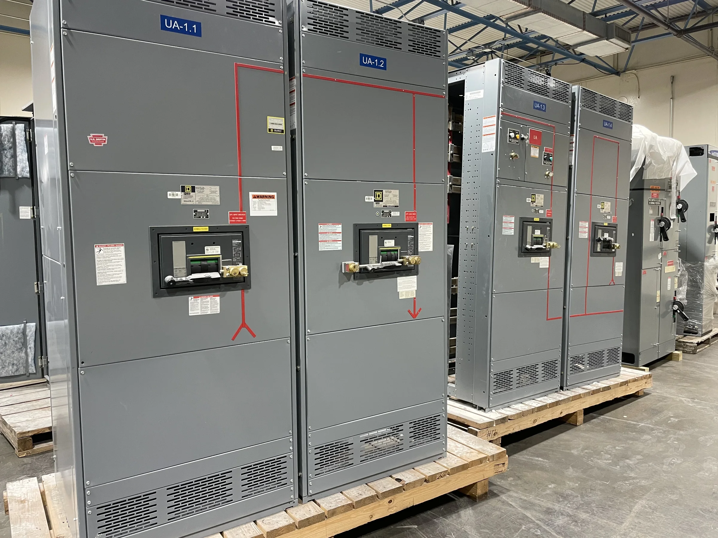
Define What “600 Amp” Means for the Assembly
A 600 amp designation is a starting point for equipment selection, not a complete switchgear specification. Confirm whether it refers to the service entrance, main device, bus rating, or a particular feeder; those ratings may differ within an assembly. The design also depends on system voltage, phase and wire configuration, available fault current, and the grounding arrangement. These details affect equipment construction, protective-device selection, and whether the proposed assembly fits the electrical system. Share the one-line diagram and load information with the manufacturer so the rating can be reviewed in context. A mismatch between the requested ampere rating and the actual point of application can lead to unsuitable equipment, redesign, or installation delays. Final ratings and compatibility are project-specific.
Match the Switchboard to the Load and Protection Plan
For a 600 amp switchboard, evaluate the connected loads and how they operate—not just their nameplate totals. Continuous loads, motor starting, future circuits, and the facility’s operating schedule can affect bus and overcurrent-device choices. Coordinate the main and feeder protective devices with the system study and the equipment they serve; interrupting ratings and available fault current must be appropriate for the installation. If selective coordination or arc-flash considerations apply, identify them early so the engineering team can review the protection scheme rather than treating the main rating as the whole design. Provide a panel schedule, load study, and known equipment data when available. The manufacturer can then develop a project-specific proposal for review, without assuming a particular configuration is suitable.


Resolve Construction, Access, and Connection Details
The physical layout can be as consequential as the electrical rating. Confirm whether the equipment is indoors or outdoors, its environmental conditions, and the intended mounting and cable-entry arrangement. Record room dimensions, door and corridor clearances, working space, ceiling obstructions, and the route from the receiving area to the final location. Cable bending space and termination access deserve particular attention: an assembly that fits on a floor plan may still be difficult to connect if conduits enter from an unexpected direction. Identify existing service conductors, bus connections, and equipment interfaces for replacement or retrofit projects. Drawings and field measurements help expose conflicts before fabrication. Final dimensions, access needs, and connection compatibility should be confirmed for the specific equipment and site.
Build a Complete RFQ and Submittal Package
A useful request for quotation gives the manufacturer enough information to distinguish firm requirements from open design questions. Include voltage and system configuration, the requested 600 amp application, main and feeder-device needs, enclosure conditions, cable entry, and any known fault-current or coordination requirements. Attach the latest one-line diagram, load schedule, equipment-room plan, and relevant utility or existing-equipment data. Note governing project specifications, required review milestones, and whether the job involves new distribution or a replacement interface. During submittal review, compare the proposed ratings, layout, connection points, and device schedule against the project documents; resolve deviations before approval. Clear documentation limits avoidable clarification cycles and gives procurement, engineering, and installation teams a common basis for evaluating the proposed assembly.
Plan Timing Around Design Review and Site Readiness
Project timing depends on more than the date a purchase order is issued. Drawing approval, design changes, component availability, and confirmation of site interfaces can all affect the manufacturing schedule. Ask for a current, project-specific schedule and identify when approved drawings, final device selections, and customer-furnished information are needed. For a replacement, coordinate outage planning and confirm that temporary power or other continuity measures are addressed by the responsible project team. Do not treat equipment delivery as permission to begin work: electrical work must follow an appropriate safety plan, including de-energization where required. A U.S. manufacturer offering custom builds and short lead times can discuss timing early, but no delivery period should be assumed until the scope and availability are reviewed.
Coordinate Shipping, Receiving, and Commissioning Records
Nationwide shipping makes receiving coordination part of the equipment plan, not an afterthought. Confirm the delivery address, site access, unloading arrangements, receiving hours, and who will inspect and accept the shipment. Verify that the route and handling plan suit the assembly’s dimensions and weight once the approved configuration is known; do not assume a loading dock or lifting equipment will be available. Before installation, compare the delivered equipment and identification with the approved submittals, and raise discrepancies through the project’s established process. Keep drawings, device information, installation instructions, and applicable test or inspection records with the facility’s maintenance documentation. For low-voltage switchboard assemblies, UL 891 requirements may apply when the assembly is appropriately evaluated; confirm the project’s exact listing and documentation requirements rather than assuming blanket coverage.