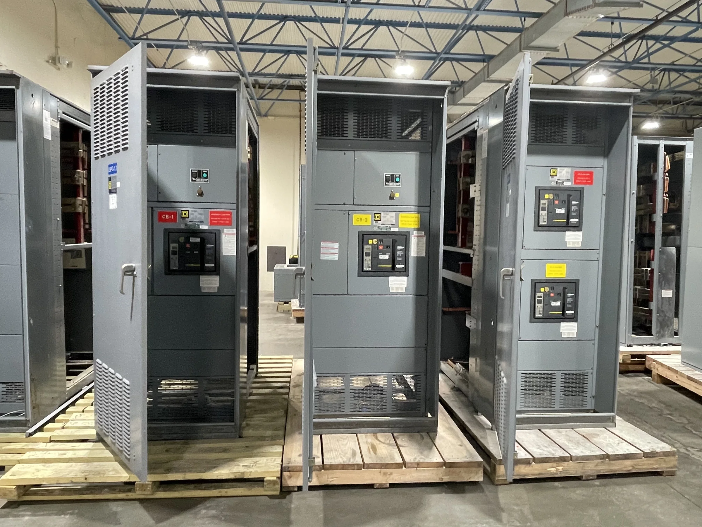
What Makes a Circuit Breaker Drawout
A drawout circuit breaker is mounted in a cradle or cell so the breaker can be moved between defined positions without disconnecting each power conductor by hand. In its connected position, primary contacts engage the switchgear’s stationary connections; in test or disconnected positions, those power connections are separated while the breaker remains supported in the equipment. The arrangement can make inspection, testing, or replacement more manageable than a fixed-mounted design, but it does not eliminate required electrical safety procedures. Control circuits, shutters, interlocks, grounding provisions, and racking mechanisms are part of the system, not incidental accessories. The exact operating positions and permitted functions depend on the breaker and switchgear design, so procurement documents should identify the intended equipment and application rather than rely on the word “drawout” alone.
How the Cradle, Interlocks, and Controls Work Together
The breaker and its cell must be compatible as a complete mechanical and electrical assembly. The cradle establishes alignment and contact engagement; shutters may cover stationary primary contacts when the breaker is withdrawn; and interlocks are intended to prevent specified unsafe or incorrect operations. Auxiliary switches and control wiring can support functions such as position indication, trip circuits, and remote operation, where included in the design. These details matter during a replacement because a breaker that appears to fit may not engage correctly, communicate the right status, or work with existing controls. Before requesting a quote, provide equipment nameplates, manufacturer and model information, breaker details, control schematics, and clear photographs where available. Compatibility and any required adaptation must be confirmed for the specific assembly; visual similarity is not proof of interchangeability.


Choose the Arrangement Around the Application
Drawout construction is often considered where equipment access, maintenance planning, or the consequences of an extended outage influence the design. A facility may value the ability to withdraw a breaker for inspection while keeping the cell in place, but the arrangement also requires space and procedures for moving and handling the breaker. Compare the application’s system voltage, available fault current, continuous current, protection functions, and coordination requirements against the equipment design; these are project-specific engineering decisions, not assumptions to make from a catalog description. Consider whether operators need local or remote control, what monitoring signals must be integrated, and how the lineup will connect to upstream and downstream equipment. A fixed-mounted breaker may suit some installations better. The right choice follows a documented system study and operating plan.
Confirm Ratings, Protection, and Applicable Standards
A purchasing specification should define the electrical duty and protection requirements before the manufacturer selects an assembly. Relevant inputs can include nominal system voltage, frequency, continuous load, fault-current conditions, grounding method, protective-device settings or functions, and the intended service environment. The required interrupting and withstand performance must be evaluated for the actual system; a breaker’s rating cannot be treated as a substitute for checking the switchgear lineup and installation. Identify applicable project standards and any required evaluation or labeling explicitly. UL 891 applies to appropriately evaluated low-voltage switchboard assemblies; it is not a blanket certification for medium- or high-voltage equipment, nor should it be assumed to apply to every configuration. The manufacturer and project team should confirm ratings, construction, standards, and any listing requirements for the exact proposed assembly.
Plan Replacement Work and Site Access Early
A drawout design does not make replacement a simple drop-in operation. Existing equipment may have different cell geometry, primary contact arrangements, control voltages, wiring conventions, interlocks, or protection settings, and a mismatch can delay installation or affect safe operation. Have qualified personnel document the installed equipment and assess the work under the facility’s safety program; electrical work requiring access to hazardous parts must be performed de-energized unless a legally recognized exception applies. Confirm outage boundaries, isolation points, testing responsibilities, lifting and handling method, door and aisle clearances, floor capacity, and the route from receiving to the electrical room. Include space for the breaker to be handled and stored during service. These site facts help determine whether replacement, retrofit, or new equipment is practical and what engineering review is needed.
Build a Quote Package That Supports Delivery
A useful request for quotation includes a one-line diagram, load and fault-current information, equipment schedule, existing nameplate data when replacing gear, control requirements, enclosure and environmental conditions, and any specified standards or submittal expectations. Add layout drawings, cable or bus entry details, room dimensions, access restrictions, preferred shipping configuration, receiving hours, unloading equipment, and the jobsite contact. Those details can affect design review, fabrication planning, shipment arrangement, and installation readiness. As a U.S. manufacturer, the company offers new equipment with American components, custom builds, short lead times, nationwide shipping, and UL 891 assemblies where applicable; exact availability, schedule, configuration, and evaluation status remain project-specific. Ask for a proposed scope, drawings, exceptions, and delivery assumptions to review before release. Early coordination helps procurement compare offers accurately and reduces avoidable site surprises.