Define the Transfer Duty Before Selecting Equipment
An automatic transfer switch (ATS) moves a load between designated power sources when its control scheme detects an acceptable transfer condition. Start selection by documenting the normal and alternate sources, the connected loads, and what must happen during loss, restoration, or abnormal voltage. A standby generator application differs from transfer between two utility sources: available fault current, source capacity, grounding arrangement, and operating sequence all affect the equipment and its integration. Identify whether loads can tolerate an interruption or require a transition method intended to limit it; do not assume every load can transfer without a break. These decisions matter because a switch sized or configured around incomplete source information may not coordinate with the upstream protection or the actual operating priorities.
Match the Switching Arrangement to Load Behavior
Specify whether the design calls for open-transition, closed-transition, or another approved transfer arrangement only after reviewing the sources, load characteristics, and project requirements. Open transition briefly disconnects a load from one source before connecting it to the other, which may interrupt sensitive processes. Closed transition briefly parallels sources, so its permissibility and controls must be evaluated against utility rules, protection schemes, and the specific system design. Motor loads, transformers, electronic equipment, and staged loads can respond differently to transfer and retransfer; simultaneous pickup may also exceed the alternate source’s practical capacity. A clear load schedule and sequence of operations help the design team resolve these concerns before procurement, rather than discovering after installation that the transfer behavior conflicts with facility operations.


Confirm Ratings, Protection, and System Compatibility
A useful RFQ identifies electrical characteristics and the intended duty without treating a nominal voltage or ampere rating as the whole specification. Provide system voltage and frequency, phase and wire configuration, available fault-current information, upstream protective-device data, and the required withstand or closing performance for engineering review. Clarify whether the switch is service entrance equipment, how neutral switching and grounding are arranged, and whether bypass-isolation or other features are required. These choices influence enclosure layout, protection coordination, maintenance planning, and the interface with the generator or utility. Final suitability depends on the complete system and applicable project standards, not on a catalog description alone. Share one-line diagrams and relevant specifications so proposed equipment can be checked against the actual installation.
Plan Controls, Alarms, and Generator Integration
The ATS is part of a control sequence, not just a power-path device. Describe how the alternate source starts, what conditions qualify it for connection, which loads transfer first, and what signal or delay governs return to normal power. Identify required remote status, alarms, communications, and connections to building or generator controls, then confirm the interface details with the equipment suppliers. A mismatch in control voltage, contact logic, or sequence can prevent a generator from starting as intended or leave operators without useful status during an outage. Include operating modes, time delays, and any load-shed priorities in the project documents. That record gives engineers, commissioning personnel, and facility staff a shared basis for reviewing behavior before the system is placed in service.
Resolve Enclosure, Access, and Installation Constraints
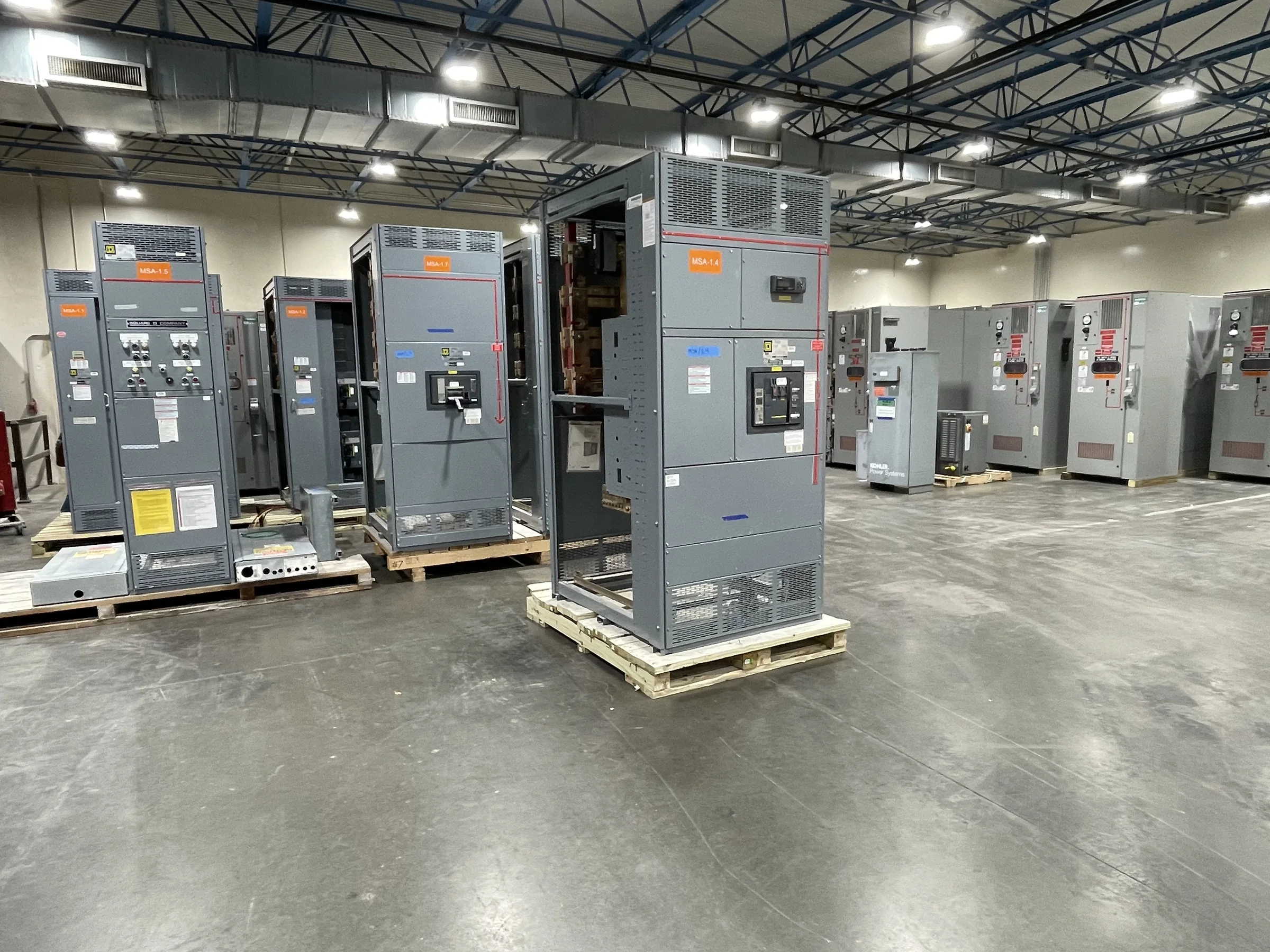
Site conditions shape a workable ATS package. Confirm indoor or outdoor placement, environmental exposure, available floor or wall space, cable entry direction, conductor routing, and the clearances required for installation and future service. Review door swing, lifting access, equipment-room routes, and the path from receiving area to final location; a switch that fits on a drawing may still be difficult to move through existing openings. Document conduit locations and connection requirements early, especially in retrofit work where existing gear and circuits constrain layout. Provide current field dimensions, photos, and updated drawings for review rather than relying on assumptions. These details support a build that can be coordinated with the site and help reduce field changes, schedule disruption, and avoidable handling problems.
Prepare a Complete RFQ and Coordinate Delivery
A complete request for quotation can make engineering review and delivery planning more predictable without assuming a guaranteed production date. Submit the one-line diagram, equipment schedule, written sequence of operation, source and load data, applicable project standards, and any required submittal format. State the requested quantity, destination, receiving limitations, preferred shipment window, and whether delivery must coordinate with a shutdown or construction milestone. For replacement work, include existing equipment identification and verified dimensions, while recognizing that compatibility must be confirmed rather than inferred from a nameplate. As a U.S. manufacturer offering custom builds, American components, short lead times, and nationwide shipping, we can discuss project-specific scope and timing. Confirm final configuration, availability, and delivery arrangements during the quote and submittal process.